It’s often said that necessity is the mother of invention, but even a casual look at early U.S. patents makes it clear that the needs were as much inventions as the inventions themselves. Did anyone ever really need a helmet with shelves inside for potted cactus plants to supply oxygen to the wearer? Probably not, but in 1986 Waldemar Anguita was granted U.S. Patent No. 4,605,000 for it. If not need, what? The British philosopher Alfred North Whitehead came closer to the driving force behind invention: “Inventive genius requires pleasurable mental activity as a condition for its vigorous exercise.”
Clay Wright found that pleasurable mental activity in imagining ways to equip small boats with pedal propulsion. “I have a strong interest in unconventional human-powered boats and enjoy sketching offbeat propulsion systems.”
 SBM
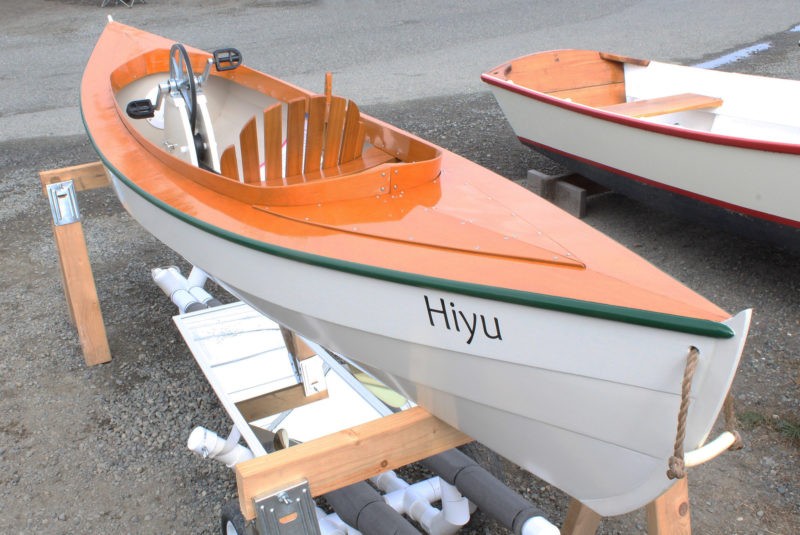
SBMClay’s HIYU is a Fiddlehead canoe, designed by Harry Bryan for double-bladed-paddle propulsion.
That interest led to his building of a 10′6″ Fiddlehead, a decked canoe designed by Harry Bryan. The canoe was designed to be used with a double-bladed paddle, but Clay had something else in mind for his Fiddlehead, which he christened HIYU.
 SBM
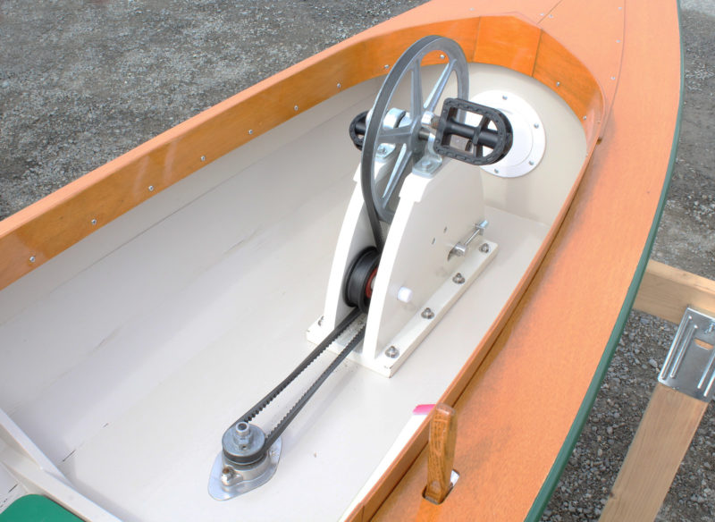
SBMThe combination of pulleys in the cockpit with the gears beneath the hull give the system an 1:11 drive ratio, so pedaling at 50 rpm spins the prop at 550 rpm.
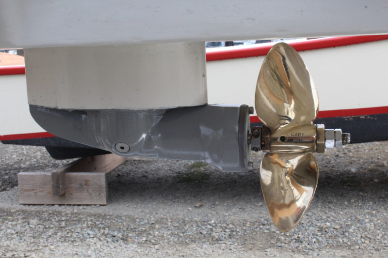
He devised a pedal drive that used a long V-belt from a large die-cast pulley on the horizontal pedal axle to a small pulley on the forward end of an outboard’s propeller shaft. On the outside of the hull was the outboard’s lower unit rotated 90 degrees with the skeg pointing forward and the driveshaft facing aft, with the propeller attached to it.
 SBM
SBMAn old outboard motor gearbox was reoriented for use on HIYU. The skeg is pointing forward and the shaft that once was driven by the motor now drives the prop.
The mechanism was simple, but there was an ergonomic problem that could be easily overlooked in the design process: “Lifting one’s horizontal leg on the upstroke of a pedal-powered boat is an issue,” Clay discovered. “The first ten minutes of any cruise I take in little HIYU makes my quads burn, and I think there is no way I can keep it up.” In time Clay grew accustomed to the unusual cycling position, but HIYU’s performance was only a qualified success. HIYU, but the way, is a word in Chinook jargon, the 19th-century trade language of the Pacific Northwest. It means “plenty,” but in this case, plenty wasn’t enough for Clay.
 Steve Navratil
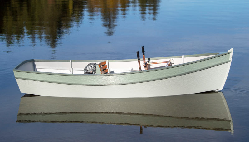
CLATAWA is a Monk plywood skiff with a few changes Clay made to enhance the boat’s curves.
He started again from scratch and built a 9′ flat-bottomed skiff, designed in the 1940s by Edwin Monk as an easily built rowboat. Clay christened the finished skiff CLATAWA, a Chinook verb meaning “to go.”
His “vigorous exercise” of invention resumed with a new focus for the drive mechanism. “My main objective was to find an alternative to rotary input, i.e. bicycle pedals, which virtually everyone who builds these vessels employs, including me with my double-ended canoe. Reciprocating foot pedals and hand levers could provide linear inputs much like an elliptical exercise machine.” Clay recognized that reciprocal motion applied to a human-powered boat would be nothing new. Another Bryan design, the Thistle, is a slightly larger boat than the Fiddlehead and is equipped with a reciprocating-pedal drive that wags a flexible fin like a fish’s tail. And the highly successful Mirage Drive for sit-on-top kayaks uses pedals that move back and forth to power its flexible fins. But as Clay noted, “I’ve never seen reciprocal motion be converted to rotary motion to rotate a propeller.”
 Clay Wright
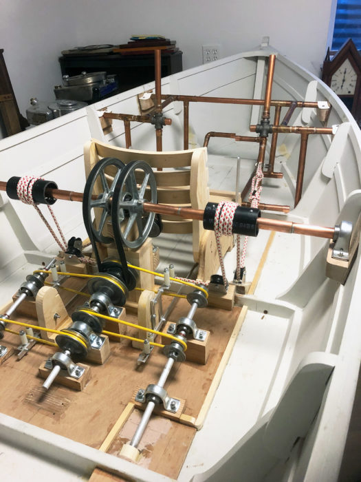
Nearly complete but still in the works, Clay’s mechanism is wonderfully complex.
Clay made a mockup with PVC pipe for the frame that would occupy the bow of the boat and support the pedals and hand levers that would supply the power to a new drive system. The skiff’s power would come from the skipper operating the system like, as Clay put it, “a seagoing elliptical exercise machine.” He followed the mock-up with construction of working mechanical systems in metal. In the shop, everything worked as it was intended to.
 Steve Navratil
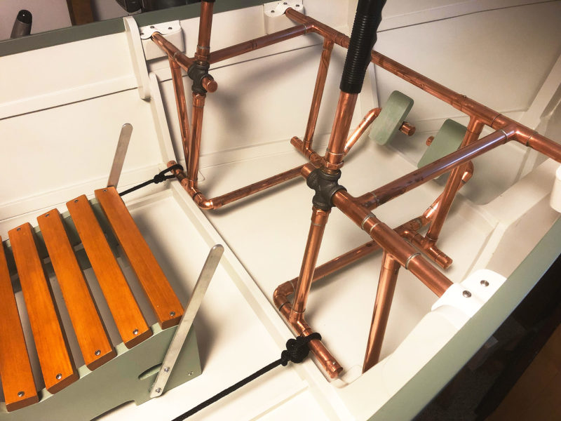
The copper-pipe pedal system has pedal pads and hand grips for leg and arm power. The levers on the seat are used for steering by shifting each propeller between forward and reverse.
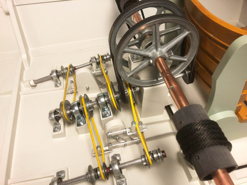
What Clay calls “the engine room” is even more complex. Here’s how he describes it: “The large pulleys are plagiarized from Phil Thiel; the near pulley is fixed to the copper shaft and therefore a driver. The far pulley is a freewheeling idler that returns the twisted V-belt. The little pulley is mounted to and drives a 1/2″ shaft which passes through the wooden tower. The aft small pulley receives the V-belt and turns a 3/4″ tube that encloses the 1/2″ shaft. Therefore, we have two shafts on a common center that are rotating opposite directions.”
 Steve Navratil
The black drum at lower right is wrapped with the cord that is connected to the pedal system in the bow. These drums are equipped with bearings that spin in only one direction. One of the large pulleys transmits the power to the center fore-and-aft shaft. The other large pulley is free-spinning. The shifting between forward and reverse is accomplished by the upright pins that move the yellow drive belts between the center drive shaft and the propeller shafts.
The yellow drive belts move to switch the prop rotation from forward to reverse. Again, here’s Clay’s description: “The horizontal bars on the clutches move the nylon rollers forward or backward to shift the belts. Note the pulleys on the propeller shaft that have one wall sawn off. Mounted in front of them are simple bearings. When either of the belts is shifted to its respective pulley, the propeller shaft is driven. The other belt is simultaneously shifted onto the bearing, where it freewheels helplessly and doesn’t drive the shaft. In this way, forward and reverse cannot be engaged at the same time.”
 Clay Wright
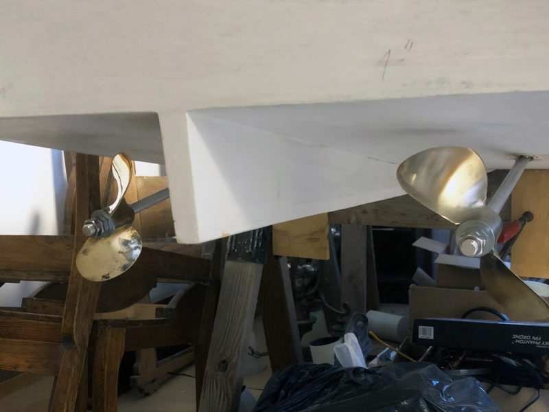
Twin counter-rotating propellers provide power and eliminate the need for a rudder.
CLATAWA’s early sea trials did not live up to Clay’s hopes. After the first outing, he reported: “I am very disappointed with the boat. She just wouldn’t cooperate. One problem after another (the drive is overly complex), weeds clogging the propellers, etc., and I could hardly get the boat to go at all. I’m feeling that the boat is a failure. The boat is back in the basement. I’m going to throw a sheet over her and try to put her out of my mind.”
 Steve Navratil
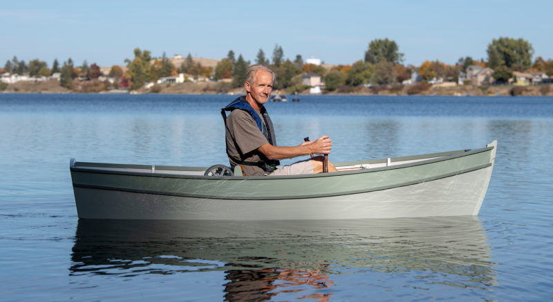
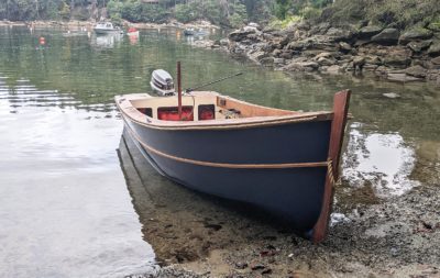
While Clay may have been disappointed with his prop drive, his boatbuilding yielded pleasing results with a shapely hull that sits in perfect trim with him aboard.
If the boat were the point of the exercise and designing the drive was simply a means to an end, CLATAWA might well be considered a failure. But it took only a few days for Clay to recall the project’s beginnings: “I concocted this admittedly impractical design for the challenge.” And he confirmed the connection between “pleasurable mental activity” and invention: “I had a great deal of fun puzzling out the challenge of converting linear movement into rotary motion.” The poor performance of CLATAWA was not a dead end but a path to escape the disappointment by taking up the challenge again.
One of the factors that had hampered the drive system’s performance was the nature of reciprocating motion: while a circular motion can continue without interruption, a reciprocating motion comes to a brief stop every time it changes direction. This isn’t an issue with the Mirage and Bryan fin drives—the fins also have a reciprocal motion and it’s what makes them work. But the propellers have a rotary motion, and they come to a stop and create drag rather than propulsion when the pedals change direction. Clay considered a flywheel to store energy and keep the props spinning in between pedal strokes. Unfortunately, he estimated that a flywheel for his drive system “would need to weigh about 80 lbs to be effective, and the boat weighs a ton as it is with all that mechanical nonsense. I think what would help the most is maximizing the pedal stroke length so the propellers would get in a good, prolonged spin before slamming to a halt. I’ll ponder a little more over the winter.”
CLATAWA’s drive system is not yet finished, but it is being worked on even if Clay is only thinking about it. The creation of something new is an essential human pursuit. The pondering is the point. ![]()
Do you have a boat with an interesting story? Please email us. We’d like to hear about it and share it with other Small Boats Magazine readers.
The reciprocal motion of a steam engine is turned into rotary motion to drive locomotives, pumps, etc. Some flywheel-type weight would have to be included in the driven wheel, but I doubt it would approach the 80 lbs. Clay noted for his complicated system. It would require a cranked axle but that shouldn’t exceed Clay’s abilities given the workmanship exhibited here.
George, thank you for your input, which I value. I never seriously considered a flywheel as it is impractical for a little boat that lives on land and needs to be toted around. The 80 lbs is just a number I pulled out of the air.
I did start out with a cranked axle. Still have all the finished parts. I abandoned it because I just couldn’t get the cranks to overcome the dead spot at top/bottom dead center. Bicycles with reciprocating cranks, locomotives, etc. have the advantage of forward momentum to carry the cranks past the dead spot, alas, propellers dragging though the water do not!
Clay
On a steam locomotive, the connection between the drive wheels and the pistons on the two sides is offset by 90 degrees, not 180. This provides continuous power to the locomotive. Perhaps an adaptation of this could help.
I tried that, too! As noted in my reply to Mr. Hume, I started out with a cranked axle. If you picture a kid’s pedal car from way back when you’ll get the idea. The push/pull was linked to a copper pipe crankshaft with a crank for each side. I couldn’t get the crankshaft to roll past the dead spot at the end of each stroke. If it was driving a wheel, for instance, that was placed on the ground, the forward momentum of the vehicle would pull the crank off the dead spot and it would be a success. Propellers dragging in the water wouldn’t provide that momentum. As for your suggestion about offsetting the cranks, I tried that, too. My arms and legs just couldn’t get it together, sort-of like patting your stomach and rubbing your head at the same time!
At one time there was experimentation with elliptical front gears for bikes. I wonder if they would be any help?
I hope my grandfather’s comment leads Mr. Wright to loads more pleasurable mental activity. George Hume, above points out that steam engines convert reciprocal to rotary motion. Almost all internal combustion engines do too, of course.
I only wish I were able to execute my mental designs concocted in the shower half as elegantly as Clay Wright’s small boats and propulsion devices.
An off-hand suggestion worth exactly nothing:what about a lightish flywheel mounted horizontally like a record turntable and geared to spin faster than the propellors? Newton’s Second Law and all that.
I think there’s merit to that. If the flywheel were spinning faster than the crank assembly it might have enough oomph to get past the sudden stop at the end of the stroke. I’ll give that some thought, but at this point I don’t want to add complication to an already over-the-top contraption. Thanks for the input!
By the way, some of my “brainstorms” come to me in dreams. I think the shower is more fertile ground. If you have mental designs, I’d encourage you to crank up the ol’ sketchpad and doodle ’em out. Chris is correct, it is a lot of fun, even if nothing material results.
Clay
George Hume mentions the 90-degree relationship of the cranks on a two-cylinder double-acting steam engine. In Clay’s CLATAWA solution, there seems to be no mechanism to prohibit operating the pedal/oar handles out of 180-degree synchronization. If the human body could stand the eccentric loads of being 1/2 way through a stroke on one side, while the other side is turning around, the machinery would work as it stands. It would be sort of like riding a bicycle with the pedal cranks at 90 degrees to one another. (Toe clips and seat belt required?)
Perhaps some additional monkey motion linkage (like one of the MANY various steam engine valve gear arrangements) could trick the back part of the machine into thinking that the front part was doing 90-degree motion while in fact it is doing the human-friendly 180-degree action.
It is true that there is nothing that prohibits beginning a subsequent stroke before the previous stroke is finished. The one-way bearings on the cross shaft allow the captain to apply random inputs to the drive and the shaft will keep turning. The trouble is one, trying to coordinate the flailing arms and legs to keep things moving smoothly and two, having a long enough continuous stroke to get some mileage out of the propellers. I did mock up a monkey motion linkage using a bicycle crank attached to the arm levers to overcome the dead spot. It was so ugly I couldn’t bring myself to complete it!
Fascinating bit of work in this invention. So there are actually four power inputs in this mechanism. But force is applied in pairs — left hand and foot, then right hand and foot.
What would it take to put hands and feet out of sync so that power would be delivered continuously?
It would take a person more coordinated than myself to put hands and feet out of sync. I have only had the boat on the water for three trials. Earlier trials were actually quite successful. Unfortunately the last trial (for this article) was so problematic that I gave a pretty pessimistic report. I think with a little more debugging and practice running it the boat will come up to my expectations of performance.
Thanks,
Clay
I have whiled away weeks of my life on such mechanisms, so I understand the appeal. Just a thought: When you walk, your hands and feet work naturally “180-degrees” out-of-sync. Apart from that, I think the lighter, faster-geared, horizontal fly-wheel would be the only viable method of making the system work better. Good luck!
Matthew
South Australia
On HIYU: the pedal issue, of using your quads to hold your feet up, is the same as most horizontal pedaled systems. A simple solution is a heel strap. They are common on recumbent bicycles and would solve your problem. Of course, the best solution would be clip-in shoes , but they would be too much for a simple design like HIYU.
A well written, fun article.
I have recieved the same valuable input from people who actually ride recumbent bicycles, which I do not. With those suggestions in mind I have thought about nailing a pair of water socks to the pedals, but the thought of being attached to the boat in the event of a capsize makes me a little squeamish. Heel straps couldn’t hurt, though,
The first ten minutes of pedaling HIYU I really feel the burn. After that, my quads resign themselves to the fact that they are going for a boat ride in spite of their complaints. After the initial period, my legs get into the swing of it and I can pedal the boat for hours. HIYU is one of the great joys of my life. I look forward with pleasure any chance I get to put her in the water.
Thanks, Clay
Are there plans available for the 9’ boat?
I only found the original plans for a bigger boat. I would appreciate any advice or direction.
Mr. Meeker,
I decided to build to this design after seeing an example of this trim little skiff in Port Townsend. The owner told me she “rowed great, towed great,” and was an Edwin Monk design. I went searching online and finally found an original old set of plans on eBay. “Plan 23” is printed on one sheet and includes instructions for the amateur builder. Ed Monk was apparently commissioned by the Douglas Fir Plywood Association for this design. The boat is built from developed plywood panels rather than traditional plank on frame, so it’s kind-of a hybrid and has elements of early stitch-and-glue construction.
Please note that I made significant changes to the appearance of the original design. CLATAWA received a curved stem rather than the straight stick of the plans. I added considerable spring to the sheer line. Most significantly I changed the topsides of the boat by cutting down the single side panel and building in a sheer strake that has a reduced angle. In doing so I reduced the beam of the boat and added (I think) interest to the otherwise slab sided craft.
I will be pleased to send the plans along to you. Perhaps if you provide the editor with your address he can forward it to me. I will stick them in the mail, happy that the plan may produce another sweet little boat from a renowned “old-school” designer. Feel free to contact me though the editor to discuss the boat. If you happen to live in the Pacific Northwest, the boat will be at the Wooden Boat Festival next year in Port Townsend, assuming the Festival isn’t canceled again!
Thanks,
Clay
You have made a beauty and I love your choice of colors. Beautiful work.
Clayton, you need an outboard motor, or simple oars 🙂
Rube Goldberg would be impressed.
Love the creativity involved.
Actually, I thought about naming the boat RUBE, but I figured nobody under 60 would get the joke. Thanks for the compliment.
Since the article was written, I have sketched out some improvements that should make the boat more successful mechanically. I’ll make a few changes over the winter and see how she does in the spring.
Clayton, all you need to do is approach the Energy Department and ask for several billion dollars to fight climate change and then hire some government-type engineers that couldn’t come up with ideas as good as those you have in your dream.
There is the Rowbike that uses rowing action of the legs to drive wheels of a recumbent bike, I think quite successfully, doing Land’s end to John o’Groats in fast time. I believe there is a ratchet , pawl, freewheel type setup. Of course the momentum of the bike carries it through the “dead” spots, but I don’t see why water flow over the prop might not do the same for you.
Find your machine very ingenious. Could be on display at the Tim Hunkin “Under the Pier Show”!
A last comment, (with no testing of my own to back it up), think if you worked out a feathering prop, maybe higher aspect, you might have a drive for almost all conditions.
Very nice machine though!