While it’s generally accepted that the right sails and sail trim will determine how close you can sail to the apparent wind, a sailboat’s progress to windward also depends on the lift and drag generated by the centerboard and rudder. How much difference does proper foil shape make over a simple rounded leading edge and tapered trailing edge, anyway? Foils operating in fluids, whether air or water, are a well-studied topic. C.A. Marchaj, in his book, Sailing Theory and Practice, discusses the theory and gives the results of actual tests of differences in foil planform (side view), cross-section shape, size, and aspect ratio (AR – length to width). Lacking other constraints, an ideal centerboard, daggerboard, or rudder blade should have a reasonably high AR (greater than 2) planform with a streamlined cross-section that has a parabolic leading edge and a thickness of somewhere near 10 percent of the chord width (the distance from leading edge to trailing edge). A thickness of 8 percent produces less drag but stalls sooner; 12 percent has a higher stall angle but produces more drag.
Exactly where the point of maximum thickness should be located is a matter of some debate. Marchaj suggests it should be at 50 percent of the chord width, halfway between the leading edge and trailing edge, but provides no data to back that up. Other sources suggest that the NACA (National Advisory Committee on Aeronautics) symmetric foil sections, originally developed during aircraft research, are actually a good fit for boat foils operating at low speeds in water. A NACA 0010 foil, for example, has a maximum thickness of 10 percent of the width of the foil, located at 30 percent from the leading edge.
Of course, there are many practical reasons why not all keels, centerboards, and rudders have high AR planforms, but the cross section for a foil of any planform should be streamlined. My personal experience of doing it wrong on one boat, and getting it right on another boat, has convinced me that the NACA sections and guidelines above provide good performance.
HORNPIPE, my first sail-and-oar boat, was an 18’ Kurylko Alaska with a standing-lug ketch rig, and sailed well enough to windward in flat water, but lost 10 to 15 degrees of pointing ability as soon as the water got choppy. I knew it wasn’t poor sail trim. Eventually I got looking at the daggerboard and analyzed it. It was only about 2.5 percent of the sail area and its thickness was only about 6 percent of the chord width, neither big enough or thick enough in my view, and in rough water it lost laminar flow and lift. When I designed my 18′ lug-yawl cruiser, FIRE-DRAKE, I gave it a thicker centerboard with a greater fraction of the sail area, about 4 percent. I also gave it a straight quarter chord line (think of the shape of the wing of a Spitfire aircraft) and a moderately high aspect ratio of about 3:1 for the planform area. To get the daggerboard foil shaped accurately and quickly I opted to have it cut on a computer numerical control (CNC) machine. All that was left for me to do was sand, seal and paint, and make an epoxy-lined hole for the pivot pin.
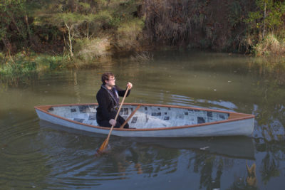
The results have been what I had hoped for. FIRE-DRAKE sails quite well to windward and maintains its performance in rough water. I sailed in the company of a similar boat—with the same length and beam, the same weight, and the same sail plan—along the south half of the Inside Passage, and that boat’s centerboard was shaped by eye. When sailing to windward, FIRE-DRAKE would consistently point higher and walk away in speed. My centerboard even let me continue sailing to windward when my partner gave up and took to the oars.
Although I had the daggerboard shaped with a CNC router, it is possible to shape a high aspect ratio, fully streamlined foil in the home shop. I’ll walk you through my second project, a kick-up rudder blade that I made at home to replace the original one I built for FIRE-DRAKE. I settled on a planform that is one-quarter of an ellipse with an elliptical leading edge and a straight trailing edge. (The shape would move the center of lateral resistance of the boat aft a few inches, and is intended to lighten the weather helm I’d experienced with the original rubber blade.) I drew the new blade with an aspect ratio of 2.5:1, with a length of 30″ (762 mm) and a maximum chord width of 12″ (305 mm), which would increase the lift and reduce the tip vortex drag.
To draw the planform shape of the quarter ellipse you can use an online graphing tool such as Desmos for a full ellipse. If you center the ellipse at zero, you can drag the two axes out until you get the aspect ratio you want. Since the graph has a grid in the background, you can then print out a screen capture of a quarter of the resulting ellipse and scale up the printed image to the actual dimensions required. If you are comfortable with computers, you can download and run Freeship (available for Windows only) which has a “keel and rudder wizard” that accurately generates several different planforms.
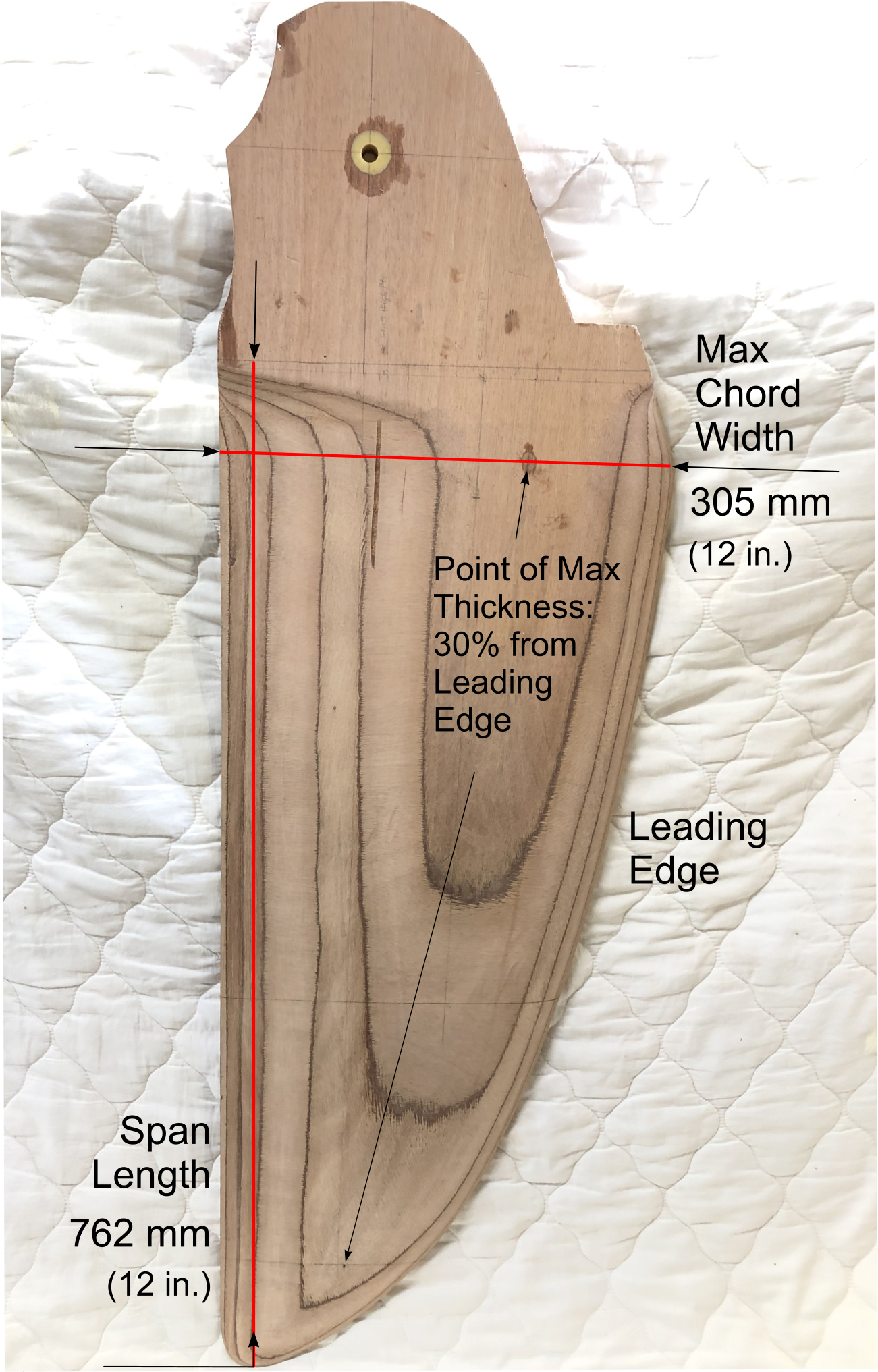
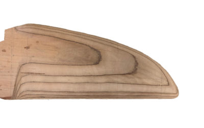
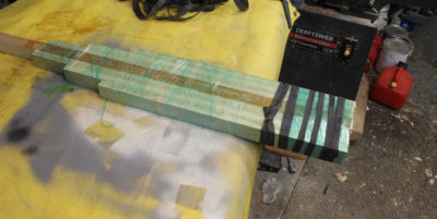
The new rudder blade for FIRE-DRAKE has a quarter-ellipse planform. The plywood’s glue lines show the contours that help with shaping the foil.
Obtaining the cross-section profile of a chord of a given width is best left to a computer. For any of the NACA foils, like the 0010 foil I mentioned above, Competition Composites Inc. (CCI) has a very simple and handy calculator. You need enter only the chord width and the maximum thickness and it will generate a table of X-Y coordinates that you can copy and print out. They’ll be your offsets for drawing a pattern for the foil cross-section. If you intend to sheathe your foil with ’glass and epoxy, for example, you can also enter the skin thickness and it will calculate the coordinates for the plywood core.
Now, here’s the tricky bit. If you have a rectangular foil planform, you only have one chord width and therefore one section profile for the entire length of the foil. However, if you have any other planform (e.g., half-ellipse, quarter-ellipse, trapezoidal, straight-chord-quarter-line, etc.), the thickness, which will be one-tenth of the chord width, changes along the length of the foil because the chord width changes.
I used the CCI calculator to generate profile coordinates for three different points along the length of the rudder blade: at the root, at about two-thirds of the way along and at about 90 percent of the way to the end. I chose those points because the chord width for my quarter ellipse planform doesn’t change much for the first half of its length, but it changes more quickly toward the tip. The idea is to shape the foil to these profiles at these points and then taper the foil evenly between them. You can lay out your foil plan directly on to the ply or you can use something thin, like doorskin, to make and fine-tune a template, which is what I did.
I made a blank for my rudder by gluing layers of marine ply with epoxy to the required 1″ thickness. I have found that the plywood, in spite of its cross-grain plies, has sufficient strength for the size of small-boat foils that I have built (though the cross-grain would weaken a long thin foil). Plywood does not warp and has the added advantage over solid wood in that the plies create a kind of contour map that give you graphic visual feedback as to the evenness of your surface once you start shaping the foil. You can make a foil with solid wood or even foam plus a ’glass-and-epoxy skin, but without the plywood laminates as guides, you would have to make more section profile templates to ensure a smooth and accurate shape.
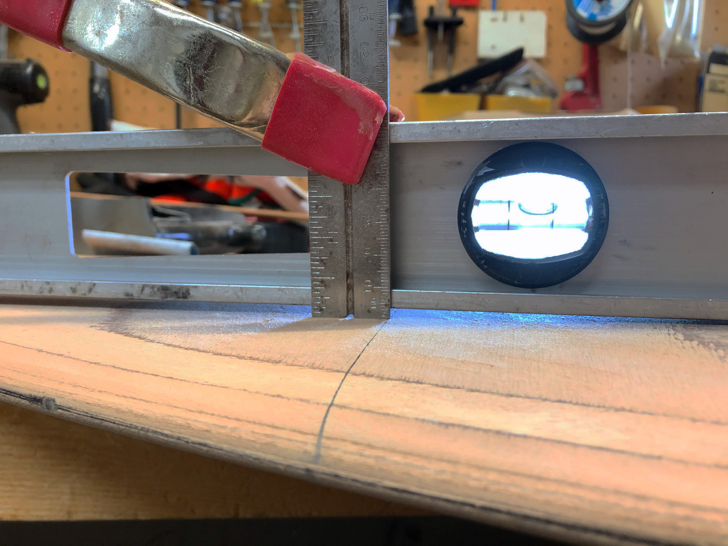
Clamping a 4′ level to the flat part of the rudder blade provides a reference line to gauge how much wood to remove to achieve the foil’s taper.
The next step is to taper the thickness of the laminated foil blank along its full length. Knowing the required thickness at your chosen points, you can draw a pattern for the curve of the taper and half the thickness of the blade stock and measure how much wood you have to remove at each point. I clamped my 4′ aluminum I-beam level to the flat part of the rudder blade above the shaped part, and used a ruler to measure the depth I had to cut to. To remove the wood for this part of the project, I used my #4 Stanley plane. While I have a power hand planer, I didn’t trust myself with it to not take too much off too quickly.
 Photographs by the author
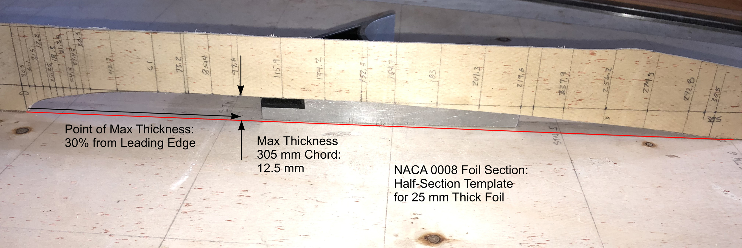
The female half-section template for a given chord for a foil gets its shape from the X-Y coordinates generated by a foil calculator.
I made three female half-section profile templates, one for each of the three points noted above, by plotting out the generated X-Y coordinates on pieces of doorskin and carefully cutting them out. One thing to note is that the CCI calculator generates a profile that has a trailing edge of zero thickness. Obviously, this is not practical to build in wood, and a knife edge is not that critical anyway. I adjusted the trailing edges so that the finished edge would end up about 1/3″ (4mm) thick.
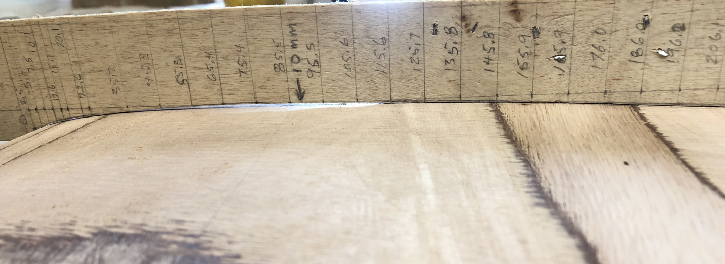
Applying the template to the foil in the works shows the high and low spots as the shaping continues.
Next, I used the profile templates to shape the foil at my three chosen points. I shaped the plywood with a Shinto rasp, regular rasps, and coarse sandpaper. It’s a process of taking some wood off, placing the template, and repeating until you get the section of wood shaped to the templates. Once that is done, I could go to work taking down the wood between the sections, using the ply layers as a guide. I used my block plane, Shinto rasp, and sandpaper for this task. I eyeballed a smooth transition around the tip from the leading edge to the trailing edge.
I sealed the surface of the shaped foil with a couple of coats of epoxy to provide a smooth, hard surface to accept a finish coat of marine epoxy enamel.
I’ve finished the rudder blade, installed it, and have taken it out for its first sea trial. The new foil definitely seems more responsive. It doesn’t require as much tiller movement to turn the boat as the old blade did and tacking seemed quicker. The effort to make the rudder blade and daggerboard with proper NACA foils has paid off with improved performance under sail.![]()
Alex Zimmerman is a semi-retired mechanical technologist and former executive. His first boat was an abandoned Chestnut canoe that he fixed up as a teenager and paddled on the waterways of eastern Manitoba and northwestern Ontario. He started his professional career as a maritime engineer in the Canadian Navy, and that triggered his interest in sailing. He didn’t get back into boatbuilding until he moved back to Vancouver Island in the ’90s, where he built a number of sea kayaks that he used to explore the coast. He built his first sail-and-oar boat in the early 2000s and completed his most recent one in 2016. He says he can stop building boats anytime. He is the author of the recently published book, Becoming Coastal.
For further reading on the pros and cons of the variables in foil design, Competition Composites (CCI) has a good discussion. For those of you who want to go into the math, Paul Zander has a good presentation from nearly 20 years ago, and also, for those inclined that way, an updated discussion with a lot more math.
You can share your tips and tricks of the trade with other Small Boats Magazine readers by sending us an email.
Is there someone who can craft a good rudder for my boat? I have not the time or the skills to do such. Have a 15′ Delaware Ducker. Love the boat but the rudder is (I think) a disaster. Hardly brings the boat around and doesn’t help much to windward. Flat plywood barn door out of 3/8″ ply with no shape other than outline that barely gets 2″ – 3″ into the water. If it could be a kick-up so much the better. I do a lot of shallow, sand-bottom sailing. Thank you for any help.
I know about the ducker and a foil shaped rudder will help a lot. Some of the modern ones built in glass and cold molded have been fitted with modern dinghy rudders and foil shaped daggerboards. They tack more like a dinghy than like my traditional one where I have to sail it around like a larger boat.
Most any small boat builder in your area should be able to build you a rudder. Lines for a kick up would be a nuisance. I don’t bother with them on a larger boat, just use a pivot bolt with tension. Means I have to shove it down.
You might want to look at the system that Mike Storer has developed for his goat island skiff, a straight foil, easier to shape.
Alex has done a great idea showing us how to work these out using hand tools. We used to do it in my dinghy sailing days by drawing a 30 % line. Make a bunch of parabola templates and hack away. For really long narrow boards before the days of carbon we used to use 5/4 stair tread fir.
Interesting article. When I built my Oughtred JII Yawl eighteen years ago, I did some research on appropriate foil profiles for the centerboard and rudder. It’s a long time ago now, so I don’t remember the exact profiles I chose, but I do believe I picked NACA 0010 for the CB. I picked another profile for the rudder, one that had a steeper stall angle, on the theory that with typical weather helm the rudder meets the flow at a steeper angle than the CB. I really don’t know how valid my theory is. I have no experimental evidence to back it up. Any thoughts?
Andrew, that seems to make sense although I haven’t seen any research to back that up.
Hi Andrew,
I remember seeing your beautiful JII; but did not ask about the foils! I wonder how NACA 0010 compares with my approximate foil shape, inspired mainly by guesswork. Are these profiles available? By the way, I do not like plywood foils; CBs break. Friends near here lost their fine old rebuilt Wayfarer; were in danger themselves, when they capsized and the plywood board broke. Too near a rugged lee shore. A class racing boat, by a particular builder – all their plywood centerboards broke.
Iain,
I don’t know what your standard foil shape looks like, but a NACA 0010 has a maximum thickness of 10% of the chord distance, occurring at 30% of the distance back from the leading edge. Marchaj believes that the maximum thickness should occur at about 50% of the distance back from the leading edge. Other designers agree, I think. If I understand him correctly, John Welsford uses a foil section that is closer to 50% distance, but I am not sure what thickness of foils he favors or what the exact foil shape is.
You can see the shape, and all the requisite numbers for extracting an X-Y plot to reproduce them, for a whole bunch of different foil types, on the Airfoil Tools site.
As for plywood foils, I understand your concern. Half the plies are oriented in the wrong direction and don’t provide much in the way of resisting sideways bending moments. However, it has been my experience that this is not a major concern if the foil is thick enough and not too long. The centerboard foil on my latest boat, for example, is ply, but is nearly 2″ (50 mm) at maximum thickness. It’s got over 1,000 nautical miles in four years under the keel by now, including a couple of practice capsizes, with no issues so far.
I don’t know what a standard Wayfarer foil looks like. Is it long and thin?
Very interesting article. I am just in the process of building a Lillistone Flint and have no experience building or knowledge of foil design and performance. I calculated the various ratios and percentages. The AR as per the plans is 2.43, so that looks good. The thickness however is only 4% of chord width. Area of the dagger board is 3.5% of sail area, so probably OK there too. Lillistone does state in the plans that the board can be made thicker if preferred so I think I may do that as 4% is a pretty big departure from the 8 – 10% of the chord width suggested. Any comments? The Flint was featured in this mag a few issues ago.
David, both my experience and authorities who design for a living and/or who have tested these things would suggest that 4% is rather too thin for good lift. I suspect that you might find it works reasonably well in dead flat water but you would lose lift and pointing ability as the water gets more turbulent.
If it was me, and I hadn’t yet built the foil and its case, I’d go for one that was at least 10% and maybe even 12%. The additional thickness would also be more robust should you need to stand on it to flip the boat over if you capsize.
Thanks so much for taking the time to reply, Alex. I have decided to use some salvaged King William (King Billy here in Tasmania) pine that was salvaged. I thicknessed it to clean it up a bit and reckon I will eventually get 20 – 22 mm out of it. I plan to laminate 10 pieces into a 304mm board. Hopefully I will get a good result.
Hi David,
It highly depends where you sail and how you sail. I have one older (1975) 420er dinghy for fun and local competitions with foiled board and rudder. But then I have 21″ German Jollenkreuzer veteran from 1952 which has both from 1/4″ steel plate, and it works fine. I sail that for pleasure on lakes. It would definitely be more performant (and point better) with both foiled, but I’m surprised how well it performs in its nearly ’70s (comparing to modern GRP boats with foiled boards).
For your job, I would probably stick to the plans. The rudder in this case is more important and can be somehow easily modified (foil). The centerboard I would keep the same, not only to conform the centerboard box (which would need to be sized), but also the overall design. Finally the most important here is what is your building and designing experience, because the worst thing is when something is incorrectly designed and then improperly built (the simple rounded plywood then may work better).
Anyway, I’m also thankful for this article. It reminds me my childhood when I built airplane models and used exactly the same methods used here to create the wings (in much smaller scale).
Hi Robert,
Thanks for your thoughts. I am going for a thicker foil and risk it (see reply to Alex above). I am well aware of risks in departing from designer’s work but I don’t think I will go far wrong.
Do SUP fins follow the rules for centerboards?
I’m not a SUP guy myself, but my understanding is that the fins are there to assist in tracking. That is, they don’t need to provide lift the way a sailboat keel/CB going to windward does.
The thing you would be aiming for in the case of SUP fins is having sufficient lateral area to provide that tracking ability, and then having it streamlined to reduce drag. I would imagine that thinner would be better, although you’d still want a streamlined foil section, as that would produce less drag than a flat plate. The leading edge of a flat plate tends to separate the flow from the sides of the plate, even if that edge is rounded, and separation produces turbulence and drag.
For twenty years, beginning in the early 1970’s, I raced a Lido 14. The boat was pre-owned, and had its original solid wood foils which were in pretty bad shape, and I decided to build new foils. After reading Marchaj’s book, and the Lido 14 Class Rules, I designed a new centerboard and rudder. The NACA-0009 section most closely fit the required class measurements, and I used that profile. I did alter the leading edge of the rudder, making it more rounded, to allow for the fact that the rudder angle of attack is variable, and is more likely to stall.
In fleet racing, and sailing close hauled, the results were astounding, with the boat seeming to sail slightly sideways, relative to other boats. I also began to pay particular attention to the condition of the foil surfaces, as Marchaj writes that the drag on underwater foils is many times greater than the drag on the hull surface. One time we were sailing in an area of submerged trees, and my centerboard lightly brushed a tree branch. I then noticed that the centerboard ‘hummed’ on port tack. Later, when I examined to board, there was a barely visible scratch.
I very much enjoyed the article on high-performance foils in the July 2020 issue of the Small Boat Magazine.
For twenty years, beginning in the early 1970’s, I raced a Lido 14. The boat was pre-owned, and had its original solid wood foils which were in pretty bad shape, and I decided to build new foils. After reading Marchaj’s book, and the Lido 14 Class Rules, I designed a new centerboard, and rudder. The NACA-0009 section most closely fit the required class measurements, and I used that profile. I did alter the leading edge of the rudder, making it more rounded, to allow for the fact that the rudder angle of attack is variable, and is more likely to stall.
In fleet racing, and sailing close hauled, the results were astounding, with the boat seeming to sail slightly sideways to windward, relative to other boats. The boat didn’t seem to point higher, when close hauled, it just didn’t make as much lee way. More benefit on the port tack, a little less on starboard. I did set the centerboard jibe angle to the maximum allowed by class rules. In all honesty, I was probably the only one in the fleet that had read Marchaj. It still took me five years to win the fleet championship.
I also began to pay particular attention to the condition of the foil surfaces, as Marchaj writes that the drag on underwater foils is many times greater than the drag on the hull surface. One time we were sailing in an area of submerged trees, and my centerboard lightly brushed a tree branch. I then noticed that the centerboard ‘hummed’ on port tack. Later, when I examined to board, there was a barely visible scratch.
I am a new subscriber to Small Boat Magazine, and look forward to each issue. Keep up the good work.
Was just about to make the centerboard for my Oughted Caledonia Yawl. So I was happy to see this article. But was then disappointed when I calculated my centerboard area to be only 1.9 percent of my total sail area. I briefly thought gee I will make it a little bigger…but then realized the centerboard trunk is already complete and limits that. I don’t plan on racing, so it is what it is.
Mark,
I’d be really interested in your results once you launch the boat and do some trials.
Theory is one thing, but nothing beats data from real-world results.
I know it’s an old article, but it’s pretty good. It does seem to conflate laminar flow and attached flow. Laminar flow usually has considerably less drag, but turbulent flow can still be attached and provide plenty of lift. Laminar flow, at least for full scale boats and airplanes, is fairly easy to disrupt, so turbulent is sometimes better. You generally need a smooth, clean surface that doesn’t have any waviness, though the overall shape is quite important, too. If you have a piece of tape, small nick, or a bit of attached algae, that is likely to disrupt the flow. On an aircraft, a bug splat is likely to leave turbulent flow. If you fly a plane or model at a constant speed, just as dew is starting, you can see this in the condensation on the wing. Viscosity is much more important with model sailboats or slow, small model airplanes, centerboard cables, or anything else that’s relatively short and slow. In that case, laminar flow may be easier to sustain, but may be more prone to separation. Imagine two really small particles in the water, 1mm and 2mm from a moving hull. At first, they will follow roughly parallel paths, but at some point along the hull, turbulence will start. Then, in attached turbulent flow, both particles will stay fairly close to the hull, but their paths will vary more, and may even cross. If the flow separates, the particles may get much farther away from the hull, before they’re even past the hull. If you’ve ever looked just behind a transom that’s getting dragged through the water, you’ve seen the consequences of separated flow.
An alternative way of making accurate foils can be found at charlesriverrc.org, where there’s an article about the accurate shaping of balsa surfaces without templates. These techniques could be adapted to wood foils. Foils like the NACA 0010 are good, though you can also draw an ellipse with two tangent lines that come together, or at least close together, at the trailing edge. This way, most of the surface of the foil is just plain flat. At low Reynolds numbers, i.e. small and slow, the thickest point should probably be about 21–23% of chord back from the leading edge. Maybe somewhat farther back for larger, faster foils that you might find on your dinghy or sailboat, as opposed to on a model. And possibly farther back than that near the surface of the water. At high lift, low pressure can actually lower the water surface or even suck in air. That may be why Marchaj, whom I have yet to read, recommends the thickest point be farther aft. It’s probably also part of why outboard motors have cavitation plates, a trick which might also work on foils that pierce the surface. You can get an idea of how prone a foil is to this “ventilation” by looking at pressure distributions for foils at the same angle of attack. There is probably pressure distribution data in “Theory of Wing Sections” by Albert Edward Von Doenhoff and Ira Abbott, easily found on line. If not, it can certainly be found in various NACA papers. Try NASA’s NTRS server,Cranfield University, or search for copies of the NACA Archive. It may be instructive to look for supercritical airfoils, meant for transonic airplanes. In that case, low pressure means high velocity. A wing at Mach 0.75 might have local flow at Mach 1, making draggy shock waves. Those supercritical foils may not be much use in a boat except one that always lifts the windward leeboard or as hydrofoils. If you find a symmetrical, supercritical foil, that might be a good choice.
Well below the surface, or, let’s say, well away from any air/water interface these things don’t matter much. How far away depends on whether you’re in a slow dinghy or a fast catamaran.
Another reason for having the thickest point further back is to preserve laminar flow longer, to reduce drag. Look at the difference between the 0010 or the Clark Y and a NACA 65- series airfoil. If you’re willing to inspect and maintain your foils after every trip around the buoys, this might make sense for you. At least if you also keep the hull smooth and clean, too.
Incidentally, when making foils it may help to draw chordwise lines on the developing foil. When you look in a more or less spanwise direction, the lines show the cross sectional shape. Alternatively, use a single, small light source and cast a shadow with a straightedge.