I share a small workshop with a picture-frame maker and, as our space has to function as workshop, small gathering space, and even classroom, our work areas must remain flexible. Power tools, worktables, and large projects—such as boats—must be movable.
Even if I were not sharing my space, being able to move a boat once the hull has been detached from its building frame has advantages. When I need to make space for other projects, maneuver long stock through table or bandsaws, or get the boat out of the shop entirely, the more easily I can move the boat, the smoother the work goes.
To meet this need, I designed and built my own mobile boat stand, one that keeps the boat steady, even during aggressive tasks like sawing, drilling, or sanding, and can support the boat whether it is upright or upside down.
Designing a mobile boat stand
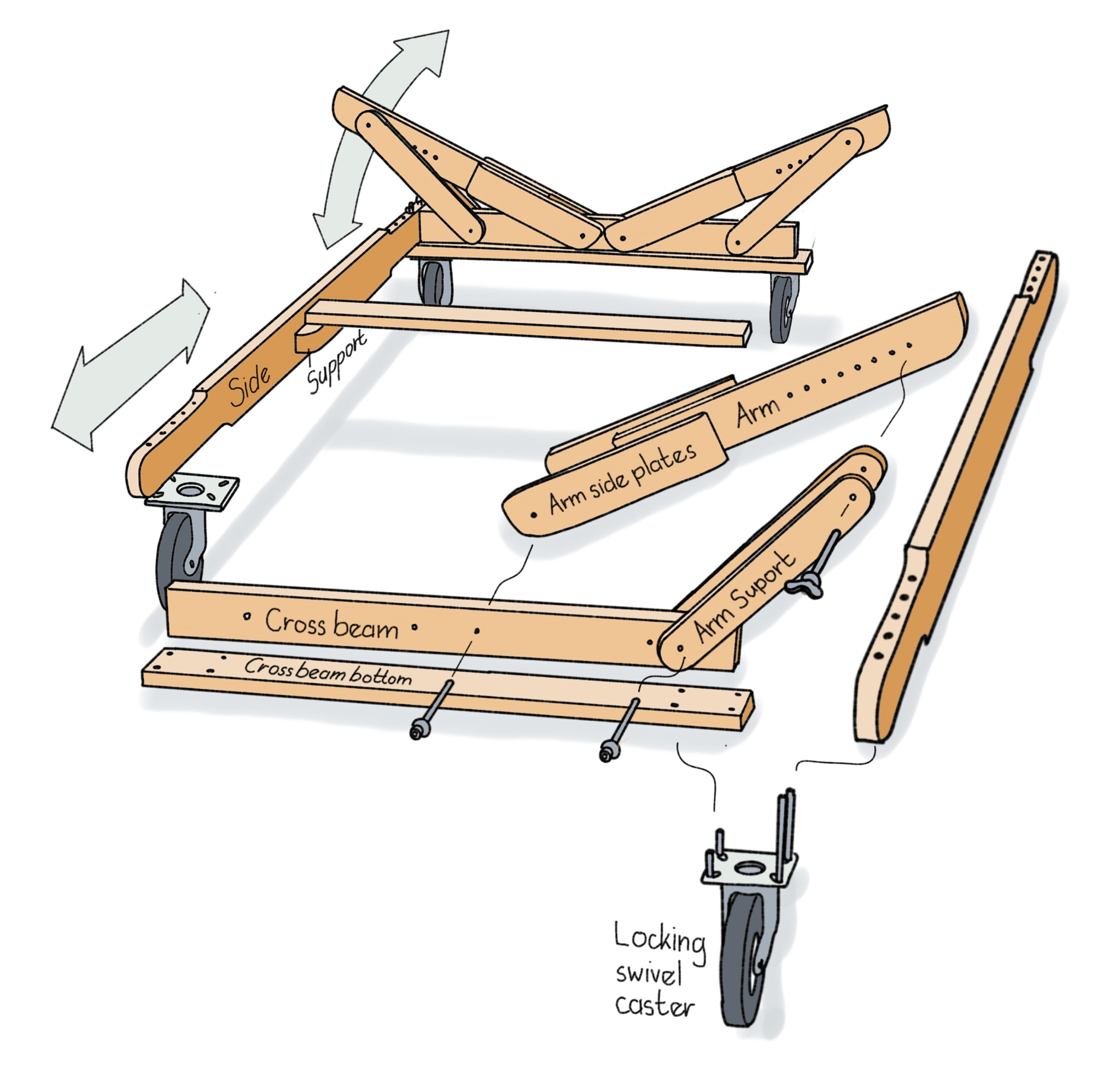
Four pivoting cradle arms support the boat and can be adjusted to fit the shape of the hull. Even if one arm is folded down to permit access to a particular area, the hull will remain stable, supported by the three remaining arms. When folded down, the arms must span the maximum beam of the hull in order to support it, upside down, on its gunwales.
 Drawings and photographs by the author
The arm side plates and cross-beam bottoms are glued to their respective arms and cross beams. All the other connections are made with threaded rod or bolts, making the boat stand adjustable to fit a variety of hull sizes and shapes.
As designed, my stand can be adjusted in length to fit boats from 2500mm (8′) to 6400mm (21′) long, and weighing up to 270 kg (600 lbs). With the dimensions given here, the arms have a span of 1600mm (63″). Because the arms are set apart from each other, they can support a hull, upside down, with a slightly greater beam. The arms could be made a bit longer if necessary.
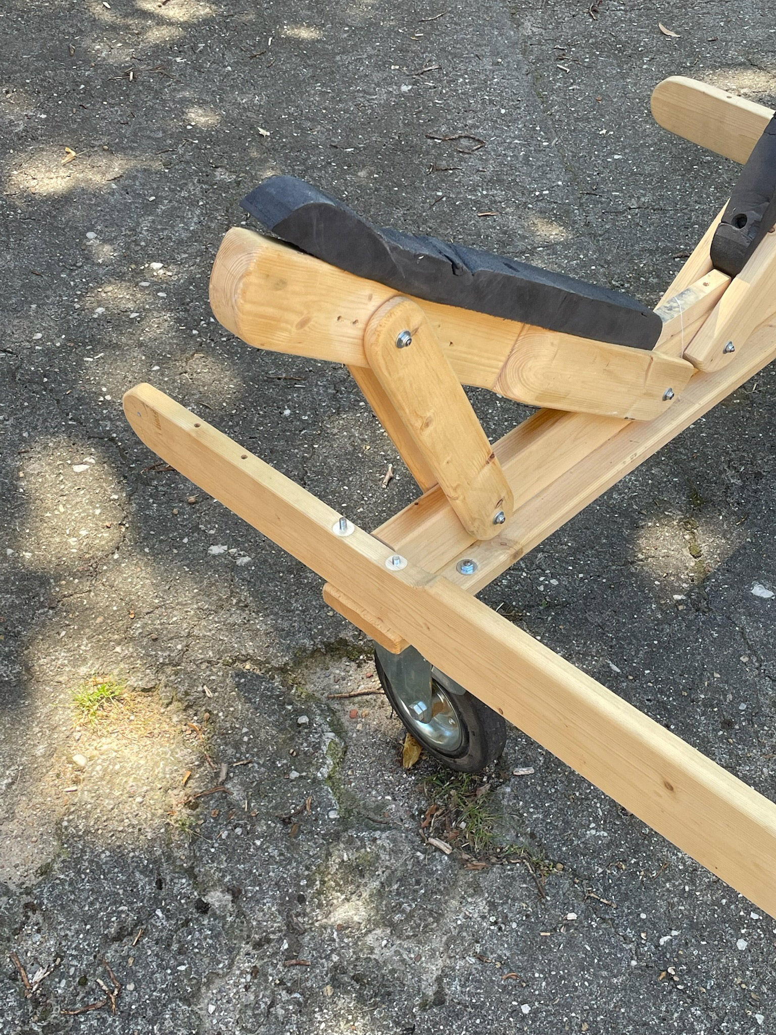
Locking swivel casters on all four corners of the bottom of the stand provide mobility when free, and steady the stand when locked. I chose 200mm- (8″-) diameter casters that can roll over the 40mm (1 3⁄4″) threshold between my shop and the yard. Smaller casters would be an option if you have no obstacles to moving the stand.
How to make the boat stand
Tools needed
Jigsaw
Drill press (optional)
Sander or sheet sandpaper
Router (optional)
Wrench for tightening nuts
Electric drill
6mm or 8mm drill bit
Hacksaw or angle grinder
File
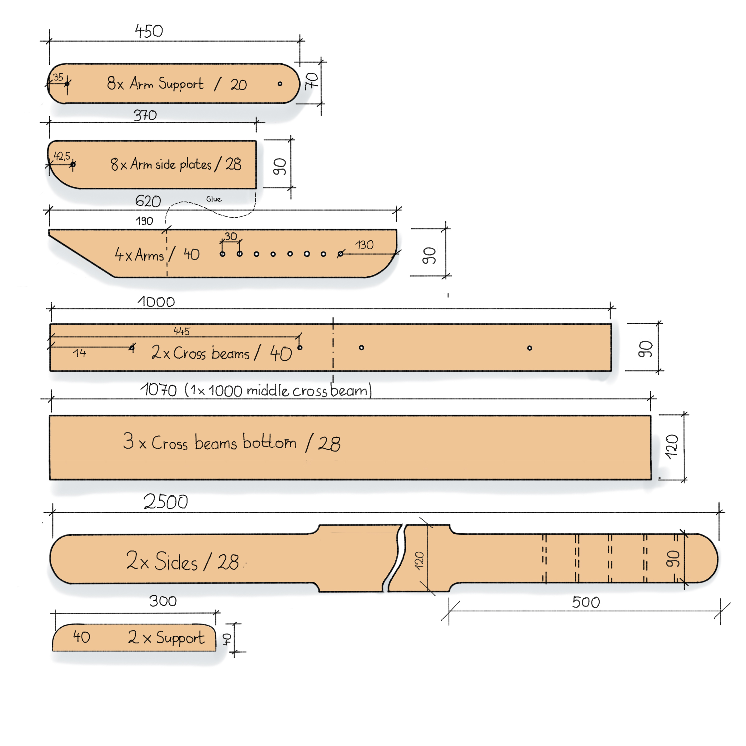
Metric parts and dimensions. The boat stand can be made from common lumber, indicated here by metric dimensions. North American nominal sizes and imperial dimensions are given below.
Materials needed
Lumber (metric here, imperial in Notes below)
120 x 28mm pine
Purchase 5 @ 2500mm
Cut:
2 @ 2500mm sides
2 @ 1070mm crossbeam bottom flanges
1 @ 1000mm middle crossbeam
8 @ 370 x 90mm arm side plates
90 x 40mm pine
Purchase 5 @ 2500mm
Cut:
2 @ 1000 crossbeams, web
4 @ 620 arms
2 @ 300 x 40 supports for middle crossbeams
70 x 20mm pine
Purchase 2 @ 2500mm
Cut:
8 @ 450 arm supports
Wood glue
The length of the cradle can be adjusted by means of the series of holes at the narrowed ends of the sides. At each corner, the caster, cross-beam bottom, and side are all connected by threaded rod cut to length or bolts of the required size.
Hardware
12 threaded rods M6 120mm
20 self-locking nuts M6
20 washers M6
4 wing nuts M6
8 threaded rods M8 50mm
8 threaded rods M8 150mm
32 self-locking nuts M8
32 washers M8
8 wood screws 4 x 50
4 locking swivel casters, 200mm diameter solid rubber tires
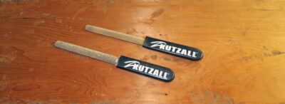
Protective padding for the arms
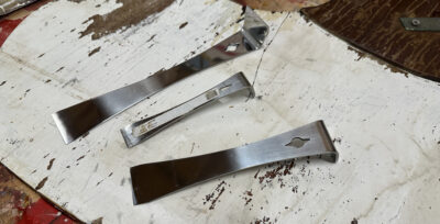
The metal pieces
While you can buy bolts for the fastenings, I cut threaded rod to length and screwed a self-locking nut with a washer onto each end. The M8 threaded rods should be measured to fit the various locations on the boat stand and cut to length during installation.
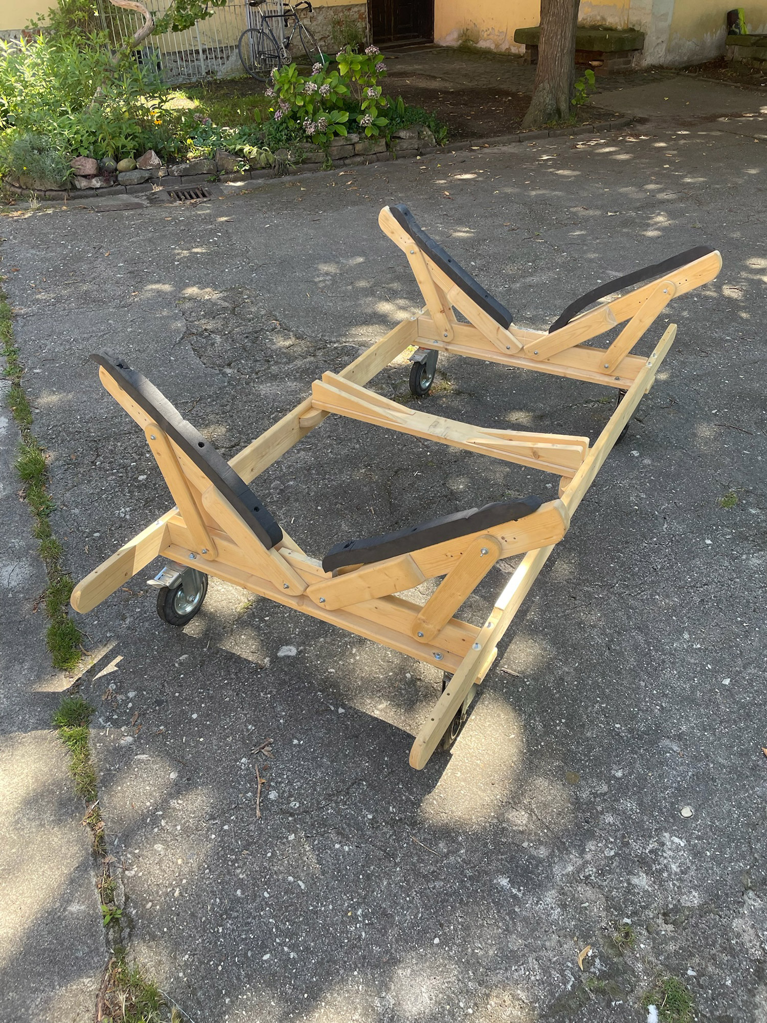
With padding on the arms, the finished mobile boat stand is ready for use.
The wood
Cut all the wood pieces to the required lengths. A chopsaw is particularly well-suited for this task, though an electric jigsaw or hand crosscut saw can also be used. Both the jigsaw and the handsaw, as well as a bandsaw, can also be used for narrowing the ends of the side pieces.
Mark the holes to be drilled before rounding the edges. The mounting plates for the casters can be offset 28mm in from the ends of the crossbeam bottoms if you are not equipped to drill the edge-to-edge holes through the ends of the side pieces.
The arms have angled inboard ends to allow them to pivot closer to horizontal. For any rounded ends, a compass, jar lids, and other round objects are suitable for marking the semicircles, which can then be cut using a jigsaw or bandsaw. The newly shaped edges can be sanded smooth.
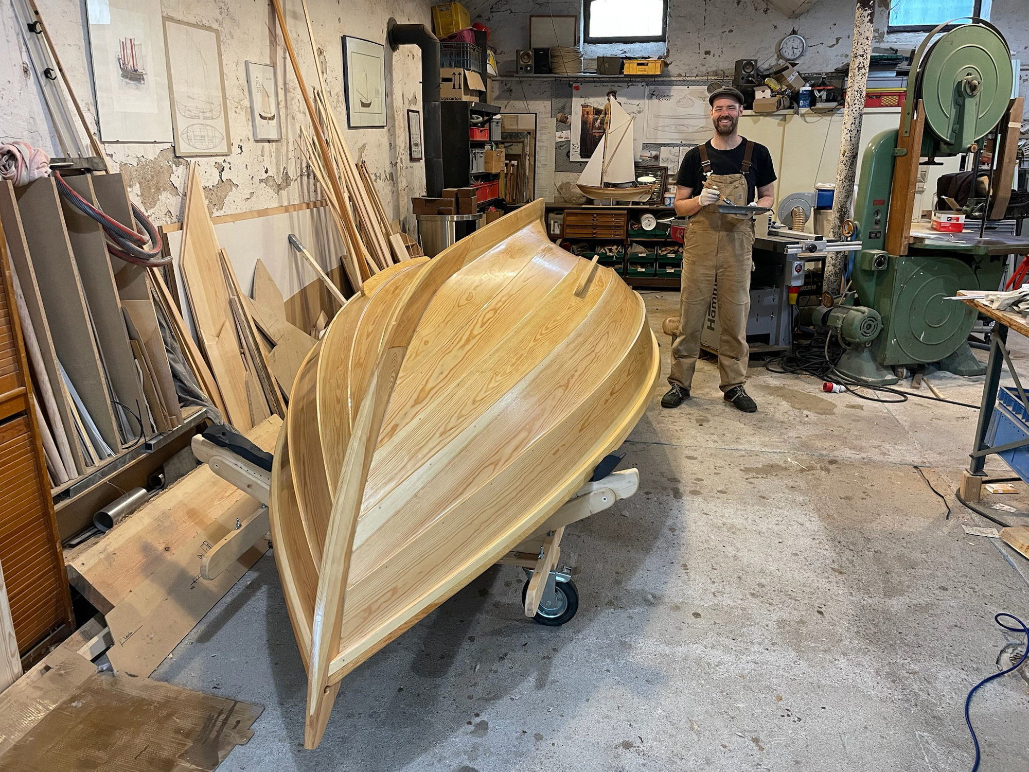
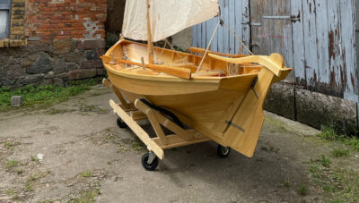
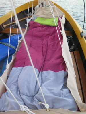
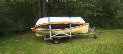
With the arms set at their lowest angle, the stand can support an inverted boat resting on its gunwales.
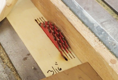
Drilling
Drill 7mm holes for threaded rods that connect the frame pieces and 8mm holes for the rods that attach the casters. Be sure to drill the holes as square to the wood as possible. This is most easily achieved using a drill press or a guide for use with a handheld electric drill. A long drill bit is required for the holes through the 120mm width of the side-piece ends. The spacing of the holes will be determined by the caster mounting plates. The threaded rod should slip easily through the 6mm holes; if the fit is too snug, re-drill the holes with an 8mm bit.
Rounding the edges
With the exception of the bottom edges of the crossbeam and the edges of the arms—which will be covered by the crossbeam flange and arm plates—I used a round-over router bit to make the edges easier on the hands when I’m moving the boat stand around the shop.
Gluing
Each crossbeam is assembled from a vertical web and a horizontal flange. The web is centered so that the flange extends beyond the ends of the web equally on both sides. The flanges can be temporarily secured to the web with screws after the glue has been applied.
Next, glue two arm plates to each arm. A 6mm threaded rod inserted through the holes in both arm plates will prevent them from shifting while the glue is setting. After the glue has cured, check whether the assembled arm fits over the web of the crossbeam. If it doesn’t, the thickness of the web can be reduced a little by sanding. If the holes do not align exactly during assembly, re-drill them.
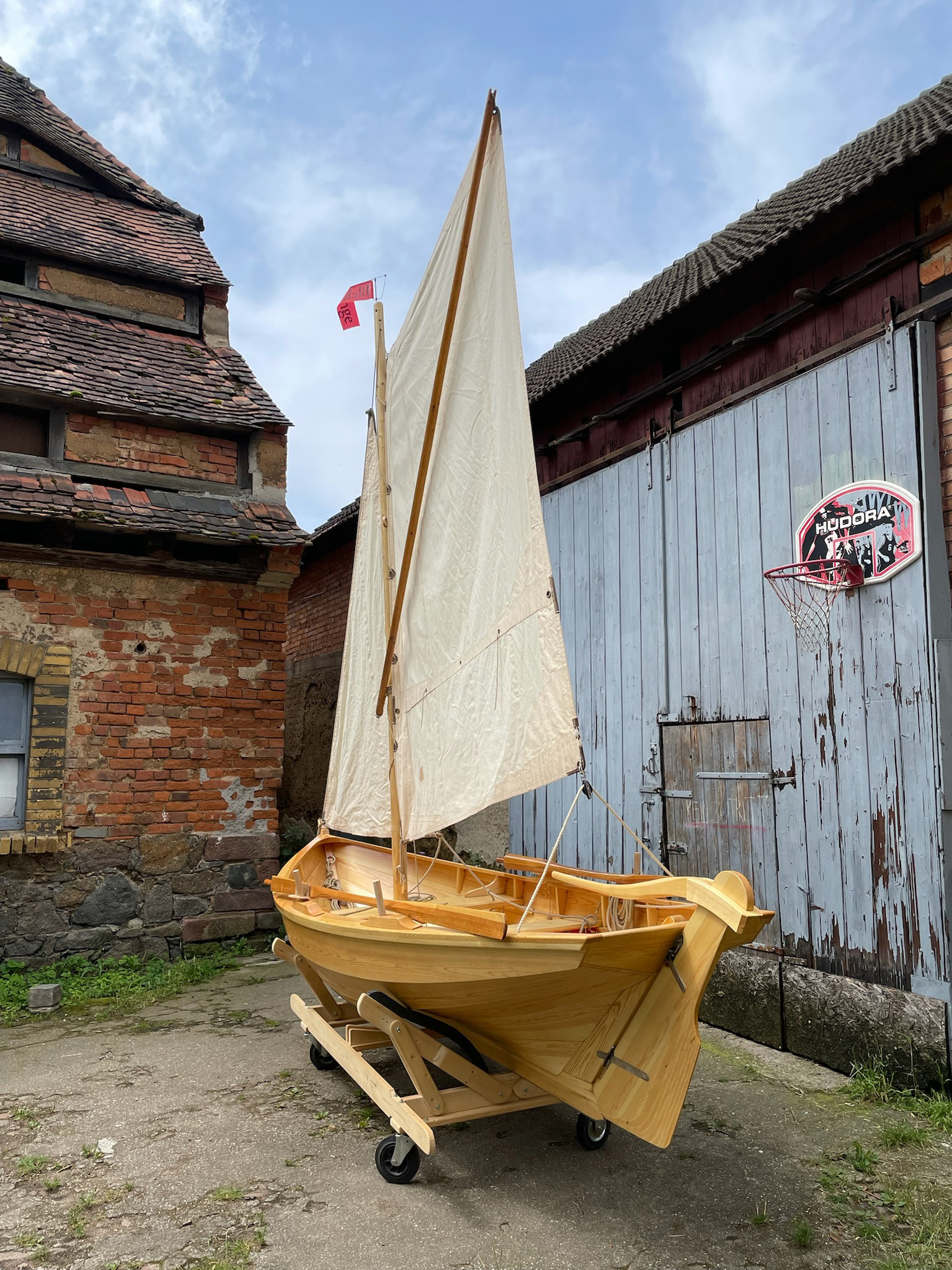
Casters with large wheels can roll over rough ground. Thus, the mobile stand—with boat—can be moved in and out of a shop in order to raise a rig or profit from natural light.
The two support blocks are glued and screwed in the middle—length and width—of the side rails. Space the screws toward the ends of the blocks so they won’t interfere with the crossbar’s fastenings.
Assembly
To assemble the structure, first connect the assembled arms to both crossbars. Then bolt in the supports. The threaded rod at the top of each support will get a wing nut so the angle of the arms can be adjusted by moving the supports’ rod along the row of holes without the need for any tools.
Next, the casters are installed to the ends of the crossbeams, each with the two inboard bolts. The two outboard bolts are then used to attach the side pieces along the row of holes to best accommodate the length of the boat. Finally, the center crossbar is placed on the two support blocks and securely bolted into place.
A bit of padding on the arms will help prevent marring the paint or varnish of a newly finished hull.![]()
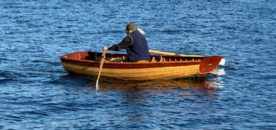
Sebastian Schröder lives near Leipzig in southeast Germany and sails in the nearby lakes of Neuseenland as well as farther away in the Baltic Sea. The boat seen in the above photographs is his Blekingsega, which he reviewed for Small Boats in September 2024.
Measurements for creating a mobile boat stand in the U.S.
Notes by Christopher Cunningham
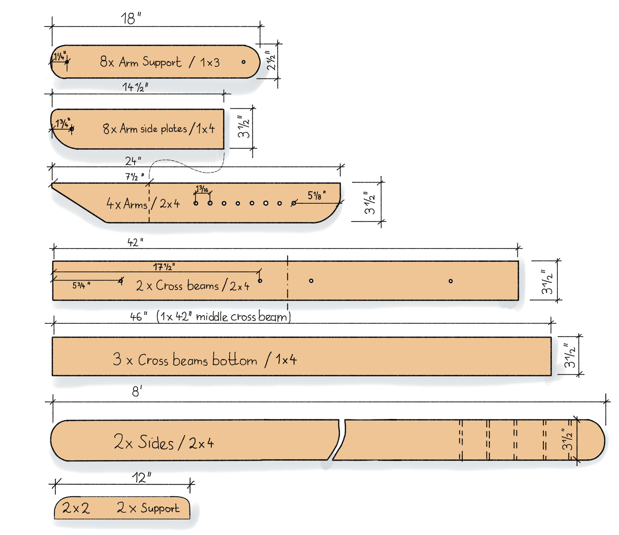
Imperial parts, nominal lumber sizes, and measured dimensions
Wood
2×4
Sides: 2 @ 8’
Crossbeams: 2 @ 42″
Arms: 4 @ 24″
2×2
Center crossbeam supports: 2 @ 12″ (can be rip-sawn from a 12″ length of 2×4)
1×4
Crossbeam bottom flanges: 2 @ 46″
Center crossbeam: 1 @ 42″
Arm plates: 8 @ 14 1⁄2″
1×3
Arm supports: 8 @ 18″
Hardware (fastenings zinc-plated steel)
For casters
Hex bolts 5⁄16″ × 18 threads per inch (tpi). (Some mounting brackets for smaller casters may have round holes for 1⁄4″ bolts. If the holes for the bolts of either size are elongated, they will accept carriage bolts for easier mounting.)
8 @ 1 1⁄2″
8 @ 5″ (if the casters are not installed under the side pieces and fastened through it, these bolts would also be 1 1⁄2″)
Nyloc (nylon locking) nuts
16 @ 5⁄16″ × 18 tpi
Washers
16 @ 5⁄16″
For arms and supports
Hex bolts 1⁄4″ × 20 tpi
12 @ 3 1⁄2″
Nyloc nuts
8 @ 1⁄4″ × 20 tpi
Wingnuts
4 @ 1⁄4″ × 20 tpi
For center beam
Hex bolts 1⁄4″ × 20 tpi
4@ 2″
Nyloc nuts
4 @ 1⁄4″ × 20 tpi
Washers
4 @ 1⁄4″
Tools
As listed above but with 5⁄16″ and 11⁄32″ drill bits.
Christopher Cunningham is Small Boats’ editor-at-large.
You can share your tips and tricks of the trade with other Small Boats readers by sending us an email.
For more articles by Sebastian Schröder, see:
Petrel Plan SG, a kit-built kayak with range and versatility.
The Åland Islands, sailing Finland’s labyrinthine archipelago.
How to Build a Brass-Frame Wind Vane, a home-made wind vane for small sailboats.


It says a lot about Sebastian when the craftmanship on his mobile boat stand is so nice. He made it functional and pretty. The boat is “stare worthy”.
Hi cybermat77 thanks for your comment, you can find out more about the boat in the article about Blekinge in the September 24 issue.
I read the excellent article you mentioned and enjoyed seeing all the pictures too. You really put the effort in on this build and it shows. Wow! Thanks