A wind vane is a useful tool on a small sailboat. This example is designed for easy removal and storage when the mast is lowered; has only a few parts that can typically be purchased at a local DIY or hardware store; is fun to make; and can be personalized to add character, featuring your boat’s name, your family name, or any design of your choosing.
Wind Vane Materials
 40mm* length of 10mm-diameter brass rod
1,000mm length of 2mm-diameter brass wire
350mm of 5mm brass rod
200mm × 500mm (or longer) uncoated ripstop nylon fabric, approximately 40g/sq m
1mm-thick brass or stainless-steel sheet large enough to cut one 90mm x 20mm piece and one 45mm × 20mm piece
2 M3 grub screws
2 stainless-steel wood screws
Tools for cutting, drilling, soldering, and shaping
*For U.S./Imperial measurements, see “How to Make a Brass-Frame Wind Vane in the U.S.” below.
Step 1: Prepare the Drilling Jig and Brass Rod Pieces
 Cut the 10mm brass rod into three pieces: one 20mm-long piece for the head; and two 10mm-long pieces for the counterweight and stopper.
Create a drilling jig using a 10mm drill bit to drill down through a sacrificial block of wood. A saw kerf along the grain across the hole will provide slack for inserting each piece of brass rod and flexibility for clamping it. Hold the block secure in a vise.
Using the jig, drill centered holes in each of the three pieces of brass rod as follows:
In the head, use a 6mm drill bit to make a 15mm-deep blind hole. Then, using a 2mm bit drill make a through-hole across the top of the rod for the 2mm brass wire that forms the frame of the wind vane. Wire diameter can vary in different batches, but I had no problem using 2mm wire and a 2mm drill; it was a perfect match. However, if the fit is too loose or tight, you can adjust by switching drill bits.
With a 5mm drill bit, drill through the stopper, end to end. (As with the 2mm drill, 5mm was perfect for the 5mm brass rod.) In the side of the stopper, drill a 2.5mm pilot hole for a grub screw. I use a cordless drill/screwdriver for tapping—it’s easier and quicker than using a tap wrench to cut threads by hand. Thread the hole with an M3 tap.
With a 2mm drill bit, drill all the way through the counterweight, from end to end. Drill and tap the counterweight for an M3 grub screw as you did for the stopper.
(If you are unable to find grub screws, use M3 stainless-steel screws, cut off the head with a hacksaw and make a groove for the screwdriver. Make sure to burnish the cut edges to keep them from damaging the nylon flag.)
Step 2: Shape the Brass Axle and Wire
 Bend the brass wire to the required shape using the measurements shown in Figure 3. Do not forget to slide the head and counterweight onto the wire before making the bends. Using a pair of round-nosed pliers, create the loop that will hold the axle, first practicing on a piece of sample wire; you will have a short offcut suitable for this once you have cut the wire to length. Bend the wire through 90° to bring it up to the top. Connect it with a loop and solder the connection. I used a 25W pencil soldering iron and solder with a very low melting point; the Sn60/Pb40 solder wire used for electronics has a melting point of around 360°F, well below the 600°F temperature that will anneal brass and soften it. I made sure the solder filled all the gaps in the joint, from both sides, and cleaned up afterwards with file and sandpaper.
Step 3: Fit the Axle
Ensure that the head is aligned perpendicular above the axle loop (see Fig. 4). Secure it by tapping a center punch or nail set on its top to pinch the 2mm wire inside.
File a sharp cone point into the top end of the axle. This point will sit centered in the dimple of the head’s blind hole.
Hacksaw a shallow groove around the axle 10mm from the bottom. The spring will push the axle to the side in the mount to engage the hole at the bottom.
Feed the axle through the loop, slide the stopper over the end, and set the point into the head. Tighten the grub screw in the stopper to set it just above the axle loop—you want the axle to stay engaged with the head but not sit against the wire below the vane.
Step 4: Create the Mounting
 Cut the 1mm-thick brass sheet into two pieces: the mount (90mm × 20mm) and the spring (45mm × 20mm).
Drill a 5.5mm-diameter hole 10mm from each of the mount’s ends and two more holes (suitable for the mounting screws of your choice) 30mm from each end. Round the mount’s ends with tin snips and bend them to a 90° angle between the pairs of holes. Drill a 4mm-diameter hole in the spring 10mm from one end. Leave this end square and round off the other end. Shape the spring in the vise so it will gently press against the axle to keep it secure.
Step 5: Prepare the Banner
Test the fabric marker on the ripstop nylon before cutting a piece for the banner—if the marker’s dye bleeds, you may not get crisp edges to the letters. Cut a piece of fabric long enough to fit your design, and at one end leave an extra 15mm on the end and along the top edge to overlap the wire frame (see Fig. 4).
With the waterproof and UV-resistant fabric marker, draw your design onto both sides of the banner, placing a pre-printed template beneath for guidance.
Sew the fabric to the wire frame.
To balance the vane, hold the axle horizontally in a vise and slide the counterweight to the point where the vane frame balances horizontally. Tighten the counterweight grub screw.
Step 6: Final Assembly

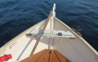
Install the mount with its spring just below the top of your mast using stainless-steel round-head wood screws. Feed the axle into the mount from above until the spring snaps into the axle’s groove to hold it in place. Step the mast and watch the wind vane turn to indicate the wind direction.![]()
Sebastian Schröder lives near Leipzig in southeast Germany and sails in the nearby lakes of Neuseenland as well as farther away in the Baltic Sea. His homemade wind vane can be seen in action in his article on the Blekinseka.
How to Make a Brass-Frame Wind Vane in the U.S.
Notes by Christopher Cunningham
To make this wind vane in the U.S., I had to find imperial equivalents of the metric sizes Sebastian used in Germany and cited in his article. Here are the materials I used.
 Wire: 3⁄32″ × 36″
Axle: 3⁄16″ × 12″ (1 3⁄4″ shorter than Sebastian’s 350mm, but 12″ is a standard length and long enough for the purpose without having to buy additional length)
Head: 3⁄8″ × 7⁄8″
Stopper and Counterweight: 3⁄8″ × 3⁄8″
Mount: 0.032″ × 3⁄4″ × 3 1⁄2″
Spring: 0.032″ × 3⁄4″ × 1 3⁄4″
Grub screws: 1⁄4″ × 10-32 Sebastian found that the 2mm wire would fit into a hole drilled by a 2mm bit and that the 5mm axle would fit the hole in the stopper drilled by a 5mm bit. However, when I drilled a 3⁄32″ hole for the 3⁄32″ wire and a 3⁄16″ hole for the 3⁄16″ axle, that wasn’t the case. I measured the brass rods with a digital caliper and found both were a few thousandths oversized. I have a set of numbered drill bits that have very small increments between sizes and found that a #41 bit was a good fit for the 3⁄32″ wire and a #10 bit fit the 3⁄16″ axle.
 Photographs Christopher Cunningham
An alternative way to drill a hole through the center of a cylinder is to turn the cylinder rather than the bit. Here, the 3⁄8″ brass rod used for the head is in the drill-press chuck and the drill bit is held stationary in a drill-press vise; the blue tape indicates the depth of the blind hole. To center the bit in the vise, put it upside-down in the chuck and lower it into the vise. Tighten the vise on the shank end of the bit and then clamp the vise to the table. Loosen the chuck, raise it, and insert the brass rod. When drilling the hole through the counterweight, you can keep the slender drill bit from wandering off-center by setting the bit as short as needed to drill the hole. That short length will be stiffer and more likely to stay on target.
The head has an oversized 7⁄32″ hole to reduce friction on the 3⁄16″ axle; it’s 5⁄8″ deep.

To drill a centered hole in the side of a cylinder, use a wooden V-block. To check that the block is centered, lower the bit into the apex of the groove. When drilling through metal, bits tend to grab as they emerge through the bottom side, making it dangerous to hold the workpiece by hand. Here, the 3⁄8″ rod is held securely in the V-block by a scrap of flat-bar and a drill-press-table clamp.
For the 10-32 grub screws, I drilled a 5⁄32″ pilot hole; a #21 bit will also work. The taps I have taper to a point that extends beyond the teeth that cut the threads. For the stopper and the counterweight, I had to drill the pilot hole all the way through to make room for that point. I tapped threads all the way through, from one side to the other, and inserted grub screws from each side.

It’s easy to make a sharp, centered point on the axle by using a drill to turn the brass rod against a spinning sanding disc.

To lock the head in place on the wire, I used a small nail set to press a dimple into the 3⁄8″ rod, pinching the 3⁄32″ wire inside of it. The dimple can be pressed into either the side or the top of the head; I chose the side as it was easier to hold the vane steady on the workbench.
I’m accustomed to using silver solder to join pieces of brass, but the high temperature required for silver solder will anneal the brass. I wanted the brass to retain its stiffness so decided not to use solder. The loop in the wire at the bottom of the frame didn’t require any solder, but at the top of the frame I needed something to keep the wire from slipping out of place. I roughed up the horizontal wire in way of the loop, squeezed the loop tight, and applied a few drops of cyanoacrylate glue.

Balancing the assembled vane so that it rests level ensures it won’t twist on its axle when it’s installed upright on a boat’s mast. Here, in order to offset the lightweight fabric banner, the counterweight is positioned close to the bottom of the vane’s leading edge. For a heavier banner, the weight would be positioned higher up the leading edge, farther from the axle.
In lieu of sewing the flag, I used permanent double-stick fabric tape.

The tail of the wind vane will fly clear of a jib-headed mainsail but may drape over the head of, say, a spritsail or lugsail if the mast does not extend high enough above the throat of the sail. The banner doesn’t need to be long to work—even the rectangle supported by the frame is sufficient—so, before finalizing the design and length of the banner, consider how much space there is above the sail.
Christopher Cunningham is Small Boats’ editor-at-large.
You can share your tips and tricks of the trade with other Small Boats readers by sending us an email.


Interesting project. Thank you.