Few things will ruin a small-boat trip faster than trailer drama, and no component of a trailer is as likely to fail as its electrical lighting system. Conventional trailer lights have it hard: they are often cheaply made and poorly wired; they are subject to the indignity of regular dunking; and they rely on the metal of the trailer and its oft-corroded bolts for their ground connection. By building an LED light bar you can ensure that the lights are properly wired, reliably grounded, and never dunked. Because of their position high up at the extreme rear end of your trailed load they are also much more visible to other drivers.
 Photographs by the author
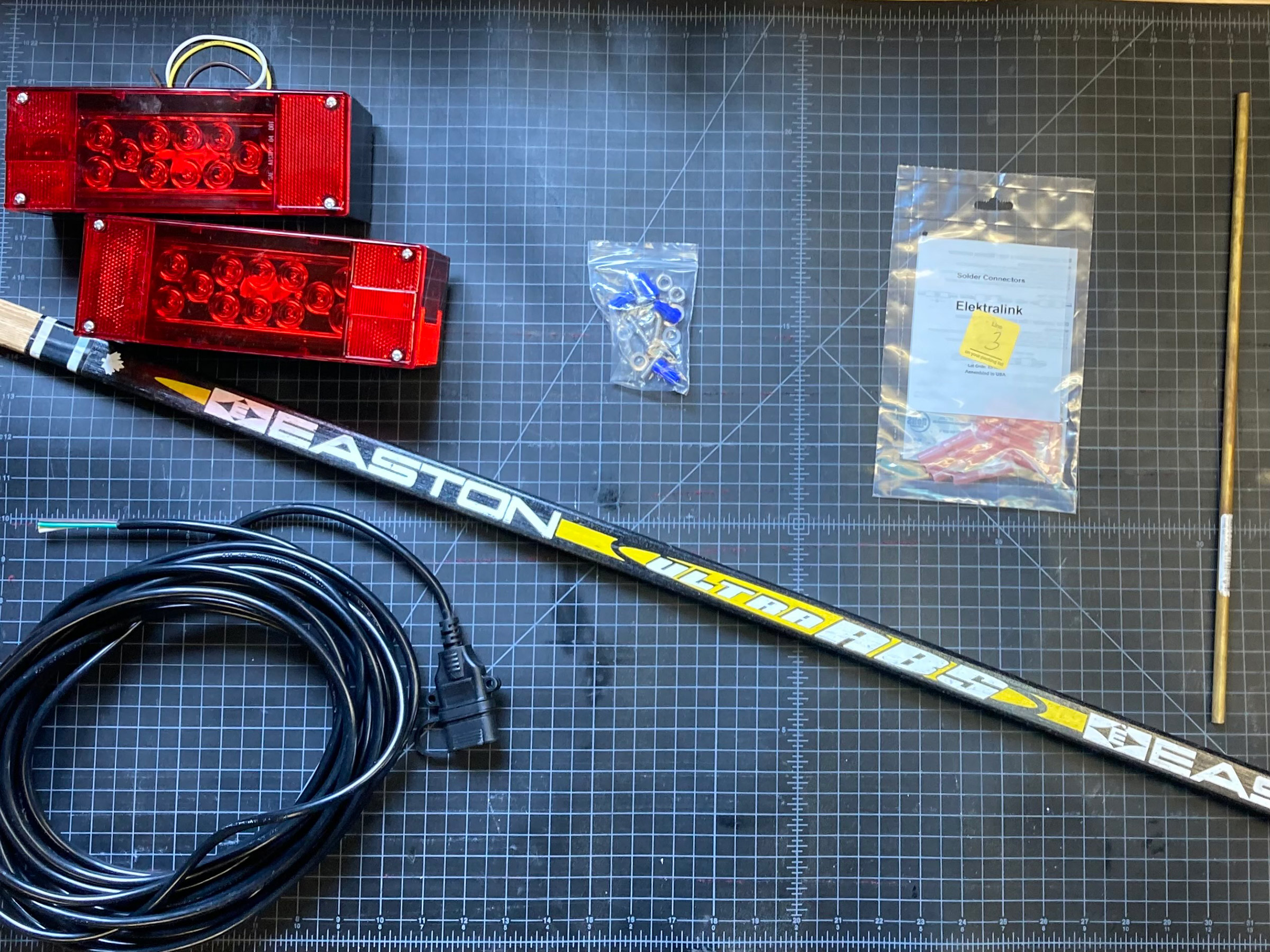
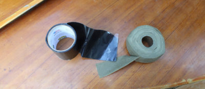
Assembly parts for a custom light bar: an LED trailer light kit, a wooden bar, a length of brass rod, a four-wire cable, some heat-shrink butt connectors, and various fastenings; the only things missing are the split sleeving and wire ties with which to attach the cables to the bar.
To build your LED light bar you’ll need the following items (the links are to products that I used, but there are many equivalents available elsewhere).
A four-wire cable as long as the combined length and beam of your boat plus 6′. A 30′ cable was about right for my 18′ pram. I recommend a jacketed four-wire cable with a flat connector. I do not recommend the flat four-wire trailer wiring kits commonly found at auto parts stores. Their white ground wires are usually cut short on the assumption that you’ll use the trailer itself as the ground; the four wires are not protected by any kind of jacket; and the individual wires themselves are often thin and unreliable.
A Y-adapter is required to supply power to the light bar as wells the trailer’s existing lights.
A bar about as long as the width of your trailer. I used an old wooden hockey stick that I pulled from the trash. It’s a hardwood laminate roughly 3⁄4″ × 1 3⁄16″. Aluminum C-channel from the hardware store also works well.
A 5′ length of slit corrugated sleeving (also known as wire loom), about 1⁄2″ inside diameter (not pictured above).
Reliable waterproof electrical connections. I recommend solder-loaded heat-shrink butt splices with an adhesive insulation.
Rudder fittings or some other way to attach the completed bar to your boat’s transom for trailering. I used a length of 5⁄16″ brass rod because it fit nicely through my 3⁄8″ transom-mounted rudder gudgeons.
Zip ties
Start by cutting the bar to length—about equal to the width of the transom—and mark the location of your upper gudgeons, usually the center. If the transom is angled, drill at the same angle for the rod that will go through the gudgeons. This will keep the lights parallel to the road. Install the rod through this angled hole and secure it with epoxy and/or peen the top of it.
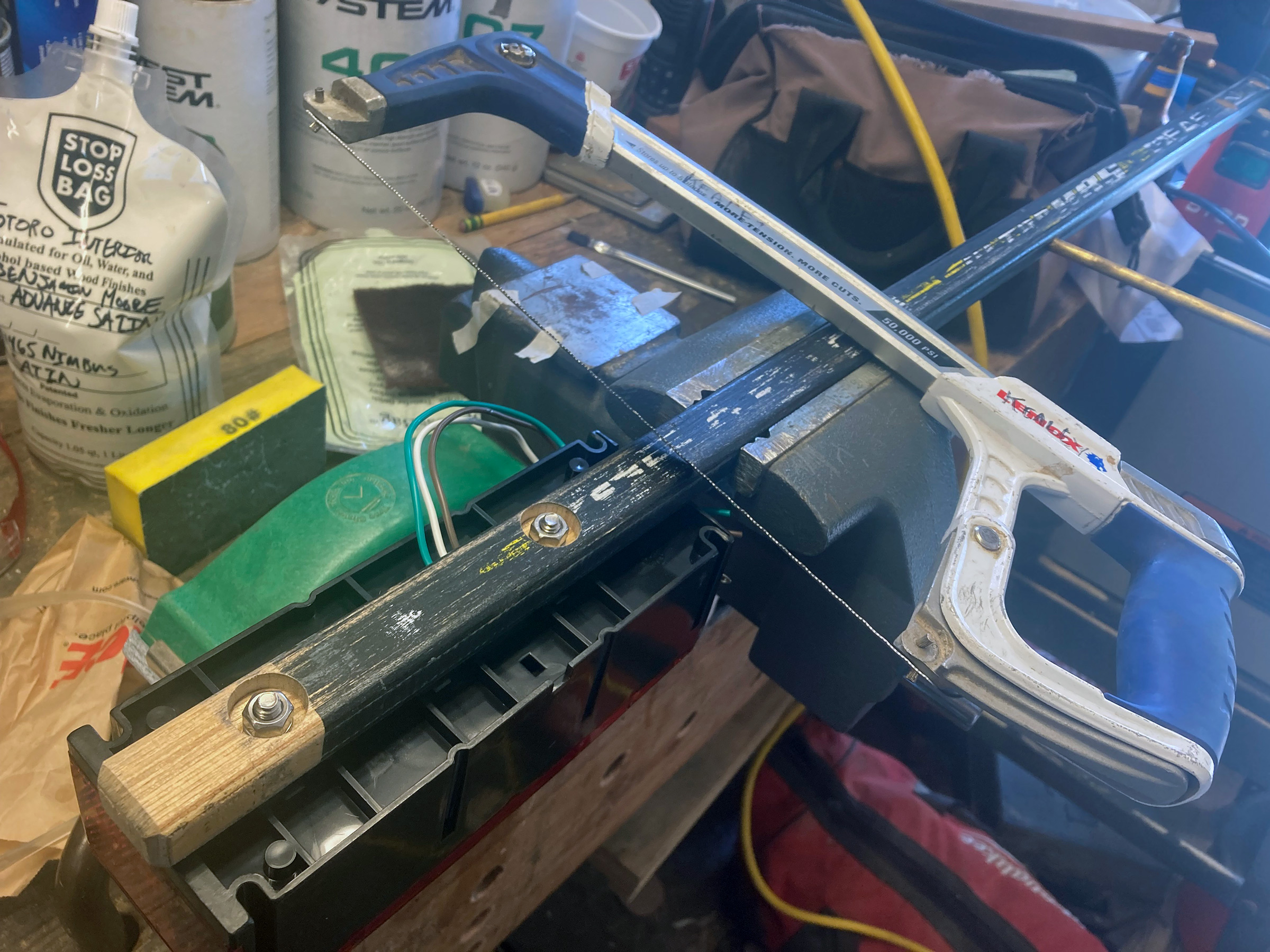
The bar is countersunk to recess the light fixtures’ mounting hardware. If the bolts protrude, they should be cut flush with the back of the bar. Here the hacksaw blade has been mounted on the frame at a 45-degree angle, facilitating the flush cut.
Drill for the light kit’s mounting bolts and test-fit the lights. The fixture with the white license-plate lamp goes on the left with the light pointing down. Bolts that protrude past the back end of the light bar should be cut flush with a hacksaw and filed smooth.
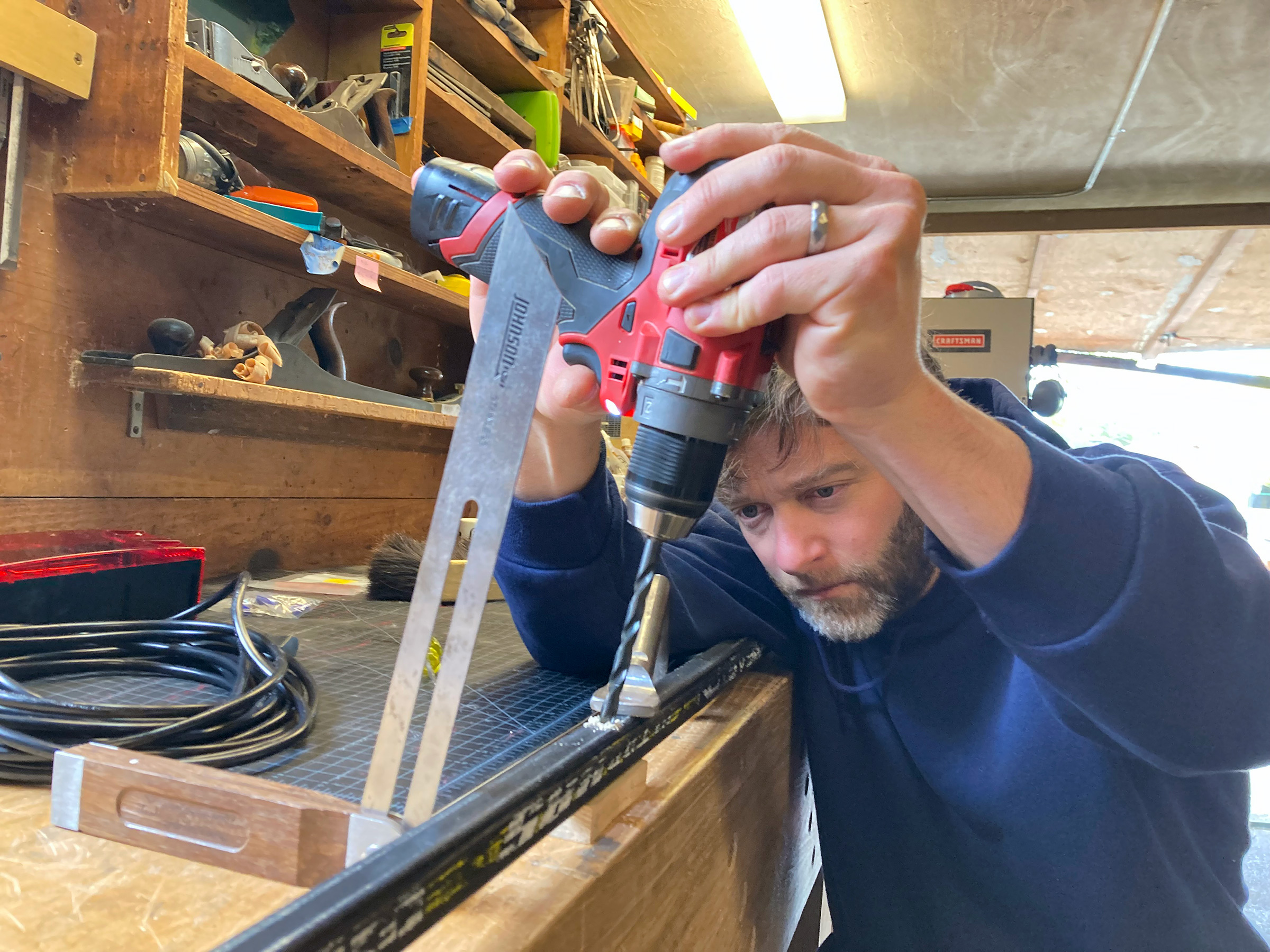
A central hole is drilled through the bar. By drilling at the same angle as the slope of the transom, the retaining rod will fit smoothly through the gudgeons and the bar will sit snugly against the boat.
Check the fit of the bar on your boat and determine how you’ll keep the bar locked in place. The same retaining clip that locks my boat’s rudder down when on the water keeps this light bar in place when we’re on the road. A tie around the bar and the gudgeon could serve the same purpose. Now is also a good time to determine how you will secure the cable to the light bar. I drilled two holes, just large enough for the cable, through the bar from top to bottom, about 1 1⁄2″ apart. The cable will make a U-turn through these two holes. With assembly and hardware complete, remove the light fixtures, then prime and paint.
Pull enough cable through the two holes in the bar to reach both lights—first one, then back across the bar to the other. Where the cable makes the U turn, a zip tie around the bar and the bottom of the U will lock it in place. Carefully strip away a few inches of the jacket where it emerges from the bar until you can see the individual wires inside. Go slowly so you don’t damage the insulation on the wires. Then gently pull the cut-off end of the jacket from the protruding wires.
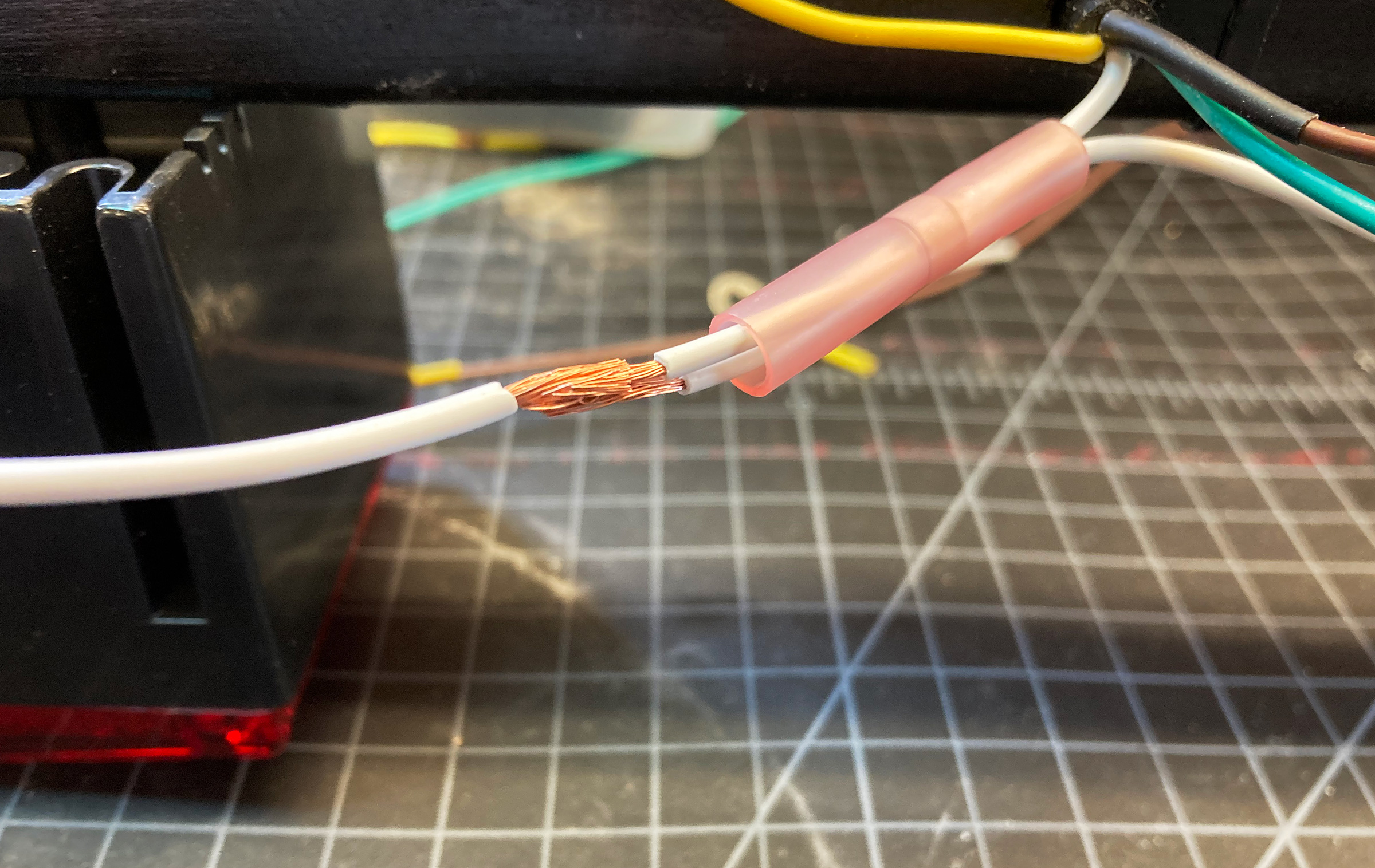
A heat-shrink butt connector is slid over two of the three wires that have had 3⁄8″ of their insulation carefully stripped away; the copper wires are spliced together before being covered by the butt connector.
If you bought the recommended four-wire cable, the connections are straightforward: everything of like color should be spliced together. Bring each wire from the cable to its matching wire on the LED lights. Cut the wires so the leads from the light fixture overlap the cable wires by about 3″ to leave some slack in the system and room for a possible rewiring in the event of a bad connection.
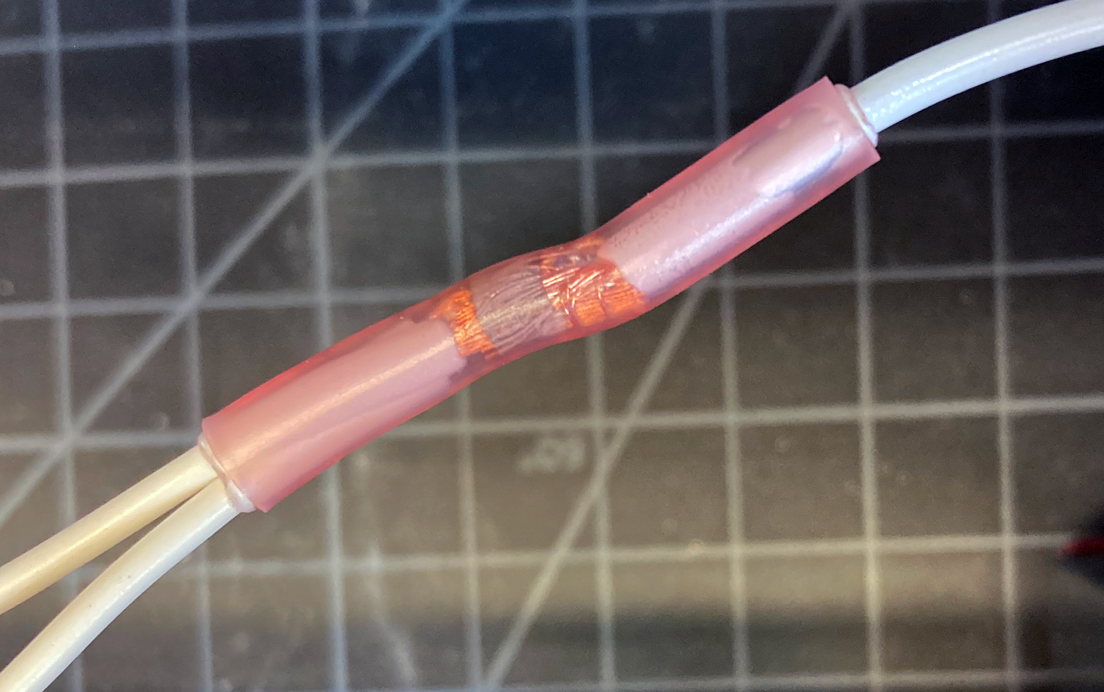
When heat is applied—from a heat gun or a flame—the butt connector shrinks around the wires. A ring of low-temperature solder melts and wicks into the copper strands, assuring good electrical transmission, and a white heat-activated adhesive within the connector melts and bonds to the wires’ insulation, making the connection both strong and waterproof.
Notice that the white wire and the red wire must be brought to both lights. I first cut the red and white wire at the length needed to connect them to the nearest light. When I connected each to its partner on the near light, I included the off-cut wire of the same color. I then carried the other end of the off-cut wire to the far light.
Your LED light kit probably came with some wire nuts or solderless splice wire connectors to make up these cables. Do your future self a favor and throw them away. Electrical connections are likely the weak link of this system; make them as reliable as possible with heat-shrink butt connectors that include low-temperature-solder. Here’s how to make the only-slightly-more-complicated three-way connection needed for the white and red wires. Start by slipping one end of the 18–22-gauge solder-loaded heat-shrink butt connectors over two of the 18-gauge wires, then strip 3⁄8″ of insulation off both wires. Holding those wires parallel, push their copper conductors into the third stripped wire. Ensure the copper strands interweave, then slide the connector back over the joint. Apply heat to the connector with a heat gun or torch. When the heat-shrink contracts around the wire, a heat-activated adhesive will make a strong bond and seal out water. Continue heating until you see the doughnut of solder melt and wick into the copper wire. The resulting connection will be secure and weather resistant.
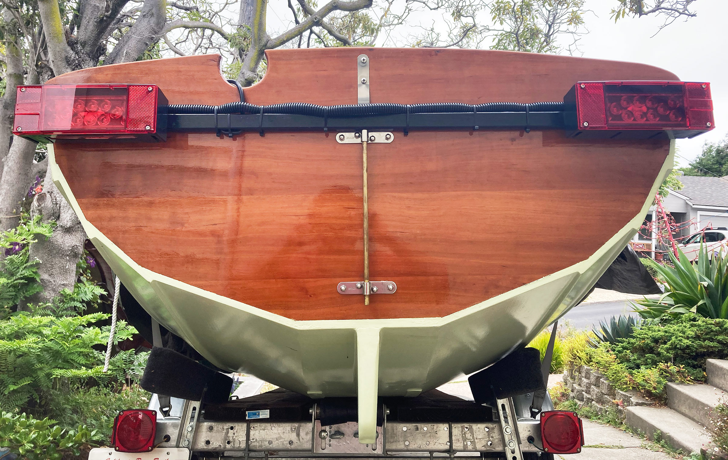
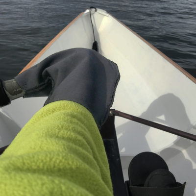
The cables, kept tidy and protected from the elements by a length of slit sleeving, are cable-tied to the light bar. The bar itself is held in position on the boat’s transom by a rod slid down through the two gudgeons. On a boat that has no gudgeons the light bar can be tied to existing attachment points.
When all six connections are completed, plug your light bar into a vehicle and check the running lights, brake lights, and turn signals. Then, protect the wiring with the corrugated sleeving. Tuck all the wires into the sleeve and secure the sleeve to your bar with zip ties and electrical tape.
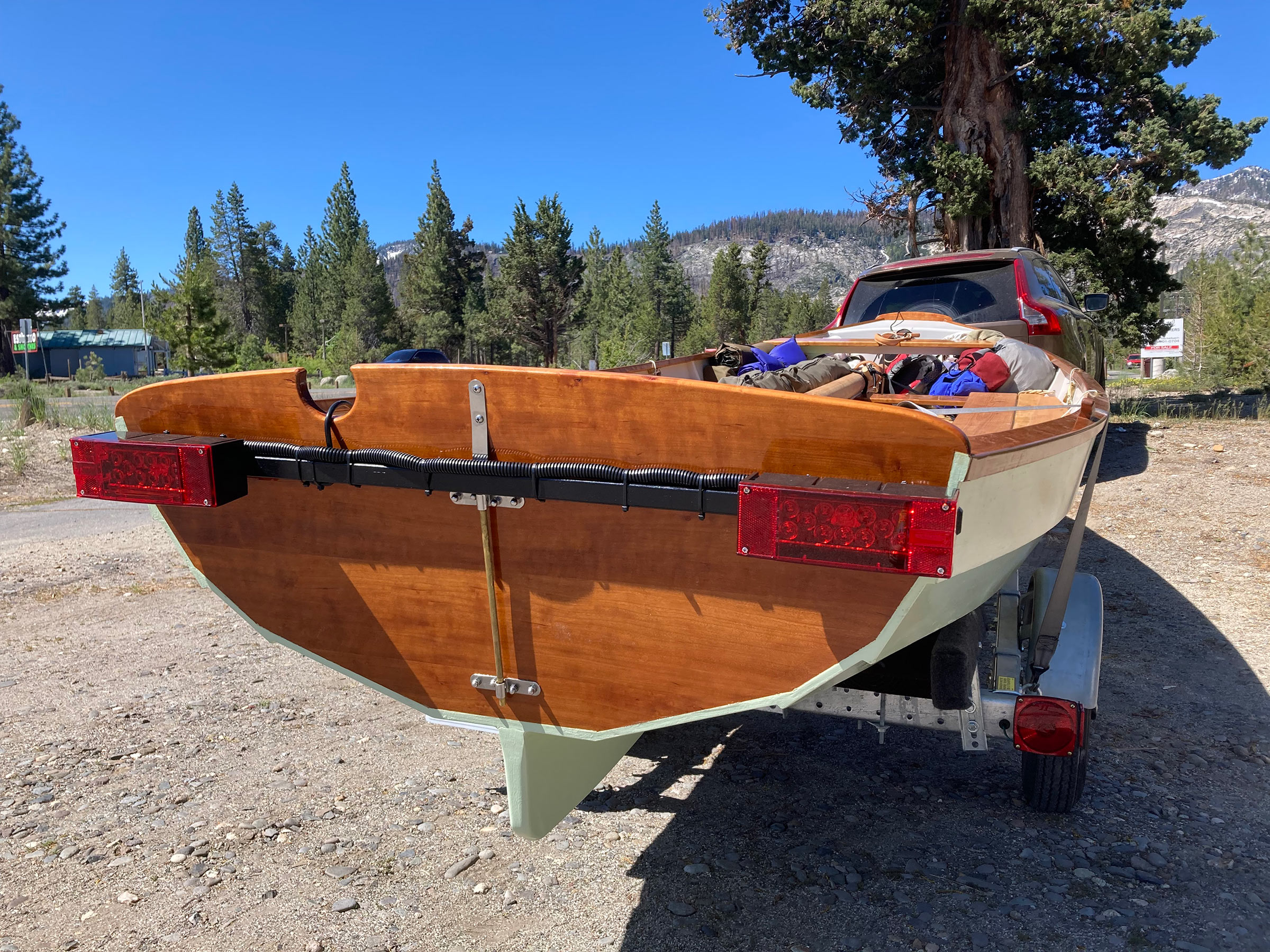
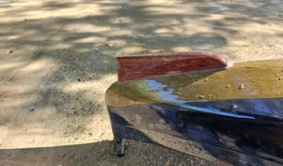
The rudder retaining clip holds the light board down and prevents it from popping out of the gudgeons. The sculling notch is a convenient channel for the light cable as it is led from the light bar to the vehicle outlet. The trailer’s original lights remain operational; it’s especially important that its left taillight illuminate the license plate as required.
Your light bar is complete and is ready to be connected the the Y-adapter that will power it and the trailer lights. It should provide years of trouble-free service and an additional measure of safety for your boat while in transit on the roads.![]()
James Kealey lives and teaches in Richmond, California. When he’s not chasing his two young sons, he can usually be found banging away on some project in his garage workshop or sail-camping on a mountain lake.
You can share your tips and tricks of the trade with other Small Boats readers by sending us an email.

Hi James,
Looks great. I wound up with something similar, but bought separate pieces as I did not know of the kits. Also I used underground-rated wire nuts instead of solder splices. The solder ones should be best, but mine have no failures in 12 years of use and may be easier to install if a heat gun was not available.
Wood hockey sticks, especially the laminated ones, are not waterproof. If you use one, varnish it well or epoxy-coat it first or it will not last more than a season or two. Better to start with an aluminum or carbon-fiber stick. All are the same price at your local hockey rink: free.
I use light bars on all my boat trailers for a couple of reasons. 1. Squirrels constantly chew any wires they can find. 2. I think regular immersion of lights hastens their demise. 3. A light bar gets my lights up higher and closer to the stern of the boat, where they are more visible. I use a 2×2 for the bar, long enough to lay across the gunwales of various boats and can be used across the rear of the trailer, if moving without a boat.